G'day,
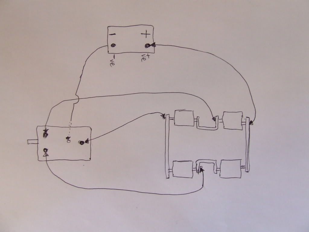
just wondering if anyone could help.. I finally got round today to mounting my winch thats been in the shed for 12 or so month.. When we originally pulled it of the other vehcle we numbered all wires an drew a diagram on a pad, so it be easy to hook back up but in the 12 months sitting in the shed the piece of paper went missing an now i go no idea which wires go where...
So after all my sob story the big question is: does anyone have a FOOL proof diagram/ Pictures of how to wire it back in..
Notice: We request that you don't just set up a new account at this time if you are a previous user.
If you used to be one of our moderators, please feel free to reach out to Chris via the facebook Outerlimits4x4 group and he will get you set back up with access should he need you.
If you used to be one of our moderators, please feel free to reach out to Chris via the facebook Outerlimits4x4 group and he will get you set back up with access should he need you.
Recovery:If you cannot access your old email address and don't remember your password, please click here to log a change of email address so you can do a password reset.
Warn 9000xp wiring HEADACHES
Moderator: -Scott-
Cant help you with a diagram but can help you work it out.
on the winch there are 4 wires.
Earth which goes straight to earth on the batt.
3 terminals marked A, F1 & F2
you will need to figure out which solenoids connect when the switch is activated. This can be done with a multimeter or by following wires.
End result you want the 12volt to switch to one of the fields (F1 or F2) whilst the armature (A) is connected to the Field (F1 or F2) that the 12 volt is not going to and swap fields for the other direction.
Hope this helps.
Matt
2000 GU ST Patrol 4.2 turbo oiler not so bog stock anymore
"EVILGU"
"EVILGU"
welcome to hammeys you beaut go fast CAD system.


while there are 3 terminals on top, the earth is the threaded hole underneath.

after you have wired it up, if you find that in is out and out is in just swap F1 and F2 around.
being a 5 pin, i can give you a wiring diagram to keep the remote and have an in cab control with an aditional switch if you want, and still keep the properties of the 5 pin setup
cheers smitty
while there are 3 terminals on top, the earth is the threaded hole underneath.

after you have wired it up, if you find that in is out and out is in just swap F1 and F2 around.
being a 5 pin, i can give you a wiring diagram to keep the remote and have an in cab control with an aditional switch if you want, and still keep the properties of the 5 pin setup
cheers smitty
innovation is better, better is faster, and fast is all that counts
Who is online
Users browsing this forum: No registered users and 1 guest