
im setting up an air tank for the maverick, i will be using 2, 12v compressors to charge it, the compressors have a max current draw of 30 amps each, now ive got a pressure switch for the tank, its a 240v job that is rated at 20amps, is this likely to go up in smoke?, if so could i run the wires from it to a relay switch which would in turn, shut down the compressor, if this is possible, what type and size relay should i ask for at the auto shop. also if someone could provide me with a rough wiring diagram it would save me a couple of head aches.
my email address is macnjay@bigpond.net.au thanks
Mark
Notice: We request that you don't just set up a new account at this time if you are a previous user.
If you used to be one of our moderators, please feel free to reach out to Chris via the facebook Outerlimits4x4 group and he will get you set back up with access should he need you.
If you used to be one of our moderators, please feel free to reach out to Chris via the facebook Outerlimits4x4 group and he will get you set back up with access should he need you.
Recovery:If you cannot access your old email address and don't remember your password, please click here to log a change of email address so you can do a password reset.
air tank pressure switch question
Moderator: -Scott-

This has been discussed several times recently on here, try a search and you should find some diagrams.
I would run Two relays off the pressure switch, one for each compressor. With a pull of 60A, the pressure switch is almost gauranteed to let the smoke out!
Drivelight/horn relays would be fine, they are rated at 30A, so one relay per compressor should be fine.
Cheers, Dean
I would run Two relays off the pressure switch, one for each compressor. With a pull of 60A, the pressure switch is almost gauranteed to let the smoke out!
Drivelight/horn relays would be fine, they are rated at 30A, so one relay per compressor should be fine.
Cheers, Dean
Just a web wheeler now!
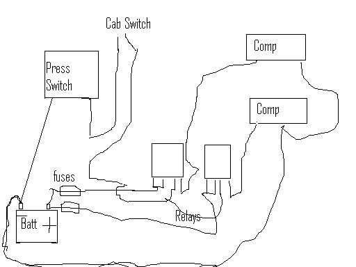
Keeping in mind I'm the worlds worst paint user, here is a rough diagram.
A few explanations-
The outside "contacts" on my relays are the load contacts, the inside pair are the switching contacts.
I have used Negative Switching to turn the relays on, this isoften a better way when running cables through a firewall and etc so if the cables chafe the unit switches on, rather than the cables exploding.
Where the wires from the pressure swtich cross the positive wires to the relays, there is no connection.
If you want the compressors to only run while the engine is running, then you need to find a positive from a ignition powered device (wiper motor, fuel pump, coil feed etc etc), and run it to the positive side of the switching contacts, instead of the positive side being jumpered straight to the positive battery feed.
I have put fuses in for a reason, so should you!!!
Cheers, Dean
Just a web wheeler now!
Who is online
Users browsing this forum: No registered users and 2 guests