Notice: We request that you don't just set up a new account at this time if you are a previous user.
If you used to be one of our moderators, please feel free to reach out to Chris via the facebook Outerlimits4x4 group and he will get you set back up with access should he need you.
If you used to be one of our moderators, please feel free to reach out to Chris via the facebook Outerlimits4x4 group and he will get you set back up with access should he need you.
Recovery:If you cannot access your old email address and don't remember your password, please click here to log a change of email address so you can do a password reset.
*WANTED* WIRING DIAGRAM FOR DRIVING LIGHTS
Moderator: -Scott-
*WANTED* WIRING DIAGRAM FOR DRIVING LIGHTS
just after a wiring diagram for driving lights,
just so i know i have done it right,
just so i know i have done it right,
bucketofbolts is sold, :(
This topic need to be in the auto elec bible. Comes up often enough....
I'm sure it has been covered before (many times) if you want to do a search.
Good place to start
http://www.outerlimits4x4.com/PHP_Modul ... ing+lights
I'm sure it has been covered before (many times) if you want to do a search.
Good place to start
http://www.outerlimits4x4.com/PHP_Modul ... ing+lights
George Carlin, an American Comedian said; "Think of how stupid the average person is, and realise that half of them are stupider than that".
Driving light wiring diagrams to make a sticky
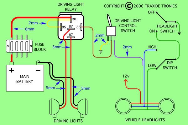
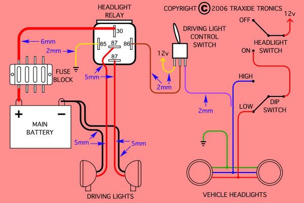
Every week people want these. These are the best examples i have seen, they were posted by drivesafe, and i downloaded them for keep sakes  Perhaps a mod could make this topic a sticky...
Positive earth: (80 series, vitaras)

negative earth: (hilux, 40 series, nissans)

Positive earth: (80 series, vitaras)

negative earth: (hilux, 40 series, nissans)

Cheers,
Dan.
[i]1996 HDJ80R[/i]
Dan.
[i]1996 HDJ80R[/i]
Re: Driving light wiring diagrams to make a sticky
Note of correction. Not truely a "positive earth". What the diagrams are referring to are "Negative switched" and the second one "Positive switched", referring to how the original headlights were swiched (RHS of both diagrams).+dj_hansen+ wrote:Every week people want these. These are the best examples i have seen, they were posted by drivesafe, and i downloaded them for keep sakesPerhaps a mod could make this topic a sticky...
Positive earth: (80 series, vitaras)
negative earth: (hilux, 40 series, nissans)
Both diagrams assume negative earth (there are no positive earth vehicles made any more).
George Carlin, an American Comedian said; "Think of how stupid the average person is, and realise that half of them are stupider than that".
Is it just me or is there something screwy with those diagrams, to do with the "Driving light control switch"????????????
For switched 12v example (pink diagram)....
Two position switch, center common.
in one position it takes the high beam 12v and powers the relay when the head light is switched to high beam (OK). Relay earthed on the other side of the coil.
In the other position it takes 12 volts and sends it to the relay at all times powering the driving lights at all times without headlights (not legal) As a matter of fact you would not be able to turn it off at all unless the switch 12v came from after the ignition switch.
The similar switching problems exist for the other diagram too.
The solution is to take the 12v (or earth) connection off the LHS prong of the switch as it is not needed.
George Carlin, an American Comedian said; "Think of how stupid the average person is, and realise that half of them are stupider than that".
Hi DAMKIA, the switches you are referring to are actually 3 position switches ( ON - OFF - ON ).
The diagrams were part of a project thread and the relevant details were posted in the thread and not on the diagram, sorry about that.
As you pointed out, the use of a 3 position switch in this form of driving light wiring installation may be illegal in some states so be warned.
As an alternative, just use a 2 position switch ( ON - OFF ) and delete the the third connection on the switch.
If you go down further in the thread you linked to, there is a diagram that will work on any vehicle and removes the need to have to find out whether the vehicle is “ negative switched “ or “ positive switched “.
Last but not least, we had so many enquires of where to get all the parts for this project that we now make a kit for any vehicle with H4 type headlights, for both a headlight wiring upgrade and a combo kit for upgrading headlights and driving lights.
Cheers
2007 TDV8 Range Rover Lux
2009 2.7 Discovery 4
2009 2.7 Discovery 4
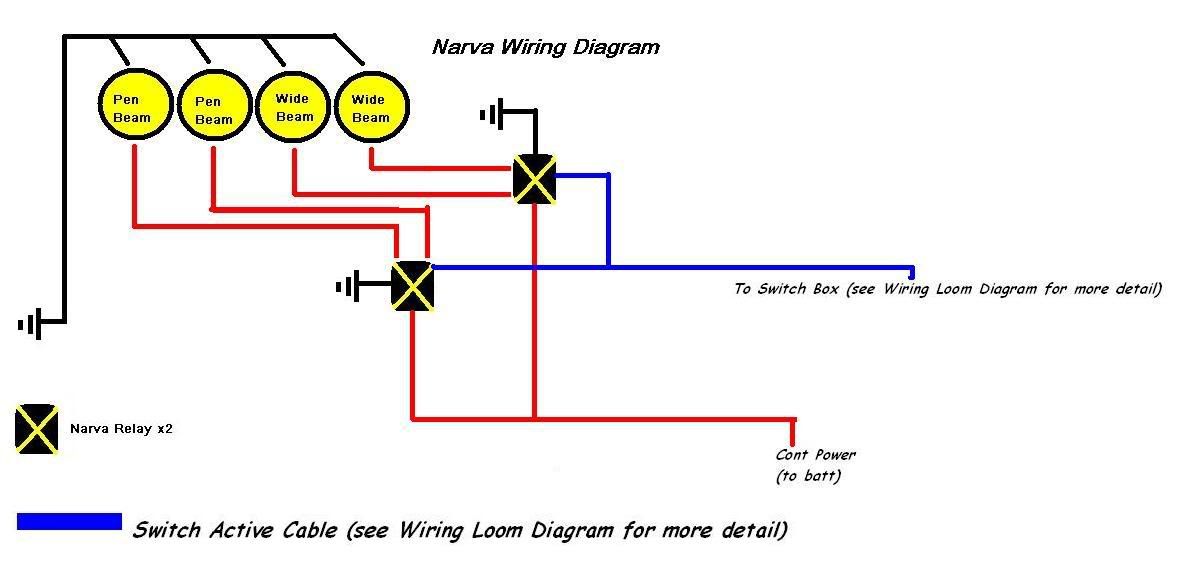
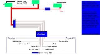
Interesting!! Thats some crazy ass setupMQSWBUTE wrote:hard wired to a switch is how i do it i dont like relays but most people do heres my own diagram
How bout a simple diode to charge both batteries without draining the other while off, most people like relays because they're fast acting switches and any switch switching current deteriorates so will have to be sizeable to do what you want, also means the fat cable has to come all the way to the switch then back out again
each to their own i guess
Wanted: Car trailer or beaver tail truck, let me know what you got
all the iso switch a red ark solinod i guess once both crankin batts are charged the redark will open and it works like altnator charges as normal will current draw from cranking batts to aux batt but with the lt supplyin power to the cranking batterys if that make sence ...aww switch actives turn on the relays so to speak so smaller cables are used but the cable between the battery and the fuse box is still of desent size
No sig line pics please.
The problem with using diodes is that the are a bit "lossy" and lose about 0.7 volt across them, meaning the batteries would either never be fully charged (if alt adoes not have a "sense" line), or that only one battery would be under/overcharged depending on the state of the other battery (if alt sense line connected to one battery past the isolator) Using diodes on the sense line would not work either as the sense line would only read the "fullest" battery and regulate accordingly.cloughy wrote:
How bout a simple diode to charge both batteries without draining the other while off, most people like relays because they're fast acting switches and any switch switching current deteriorates so will have to be sizeable to do what you want, also means the fat cable has to come all the way to the switch then back out again
You can get them (diode isolators), it has been done (to death), and was found not to be an acceptable solution when one battery was run down consistantly.
George Carlin, an American Comedian said; "Think of how stupid the average person is, and realise that half of them are stupider than that".
Who is online
Users browsing this forum: No registered users and 1 guest

