Page 2 of 3
Posted: Tue Mar 16, 2010 10:03 pm
by Z()LTAN
$60 mate.
U have to have the intake manifold on to fit the inj lines that may be an issue for you mate.
Posted: Sun Mar 21, 2010 8:57 pm
by ledgend80
ok well i have finally come up with how i will finally mount the cooler to the manifold. i had to flip the cooler 180 degrees front to back. so that the cooler can be mounted more to the passanger side of the car to allow me access to the injector lines. (thanks z()ltan for the heads up. as you can see from the pics i have had to rasie up the top plate to allow air to get into the cooler from the turbo. there will also be a funnel fitted here as well. will just have to get a little pipe bender to bend the dipstick tube. and re do the accelarator (may do like z()ltan has done) also have another idea.
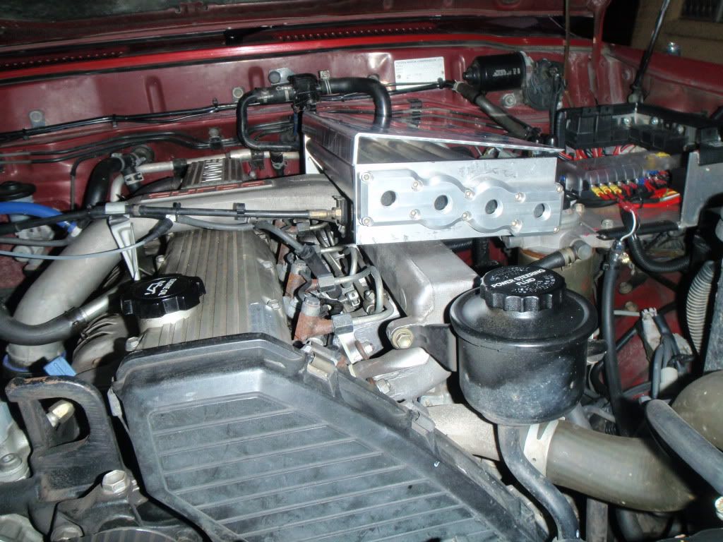
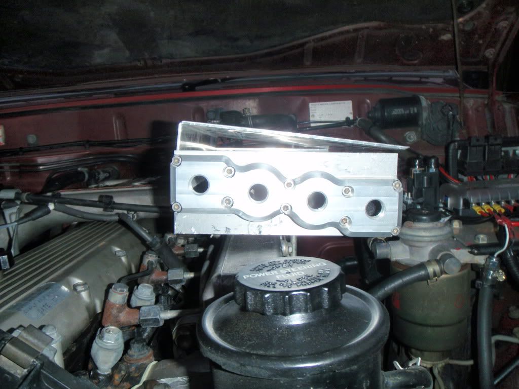
will try and get the ally bent up this week so i can see how it will all look.
if anyone can see any other problems i may have let me know
Posted: Mon Mar 22, 2010 7:07 pm
by rowenb
Can you run the throttle cable along the fire wall (new and longer one) and come in from the opposite direction and at the same time take the top off the arm or make another setup off the fuel pump? You don't really need the standard one do you?
Posted: Mon Mar 22, 2010 11:31 pm
by Z()LTAN
I looked at coming in from the back but it wont work, your trying to pull the wrong direction on the belcrank.
You could try and pull directly on the governor linkage though.
Posted: Thu Mar 25, 2010 10:25 pm
by ledgend80
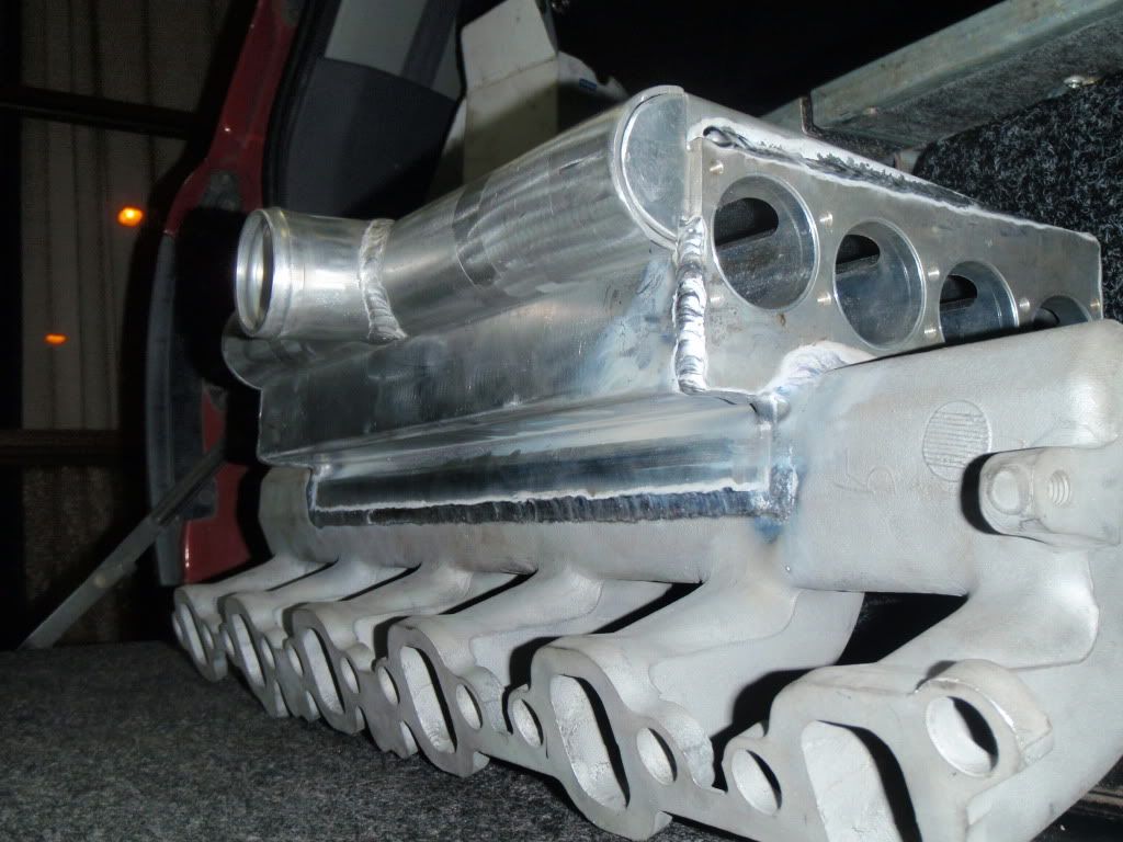
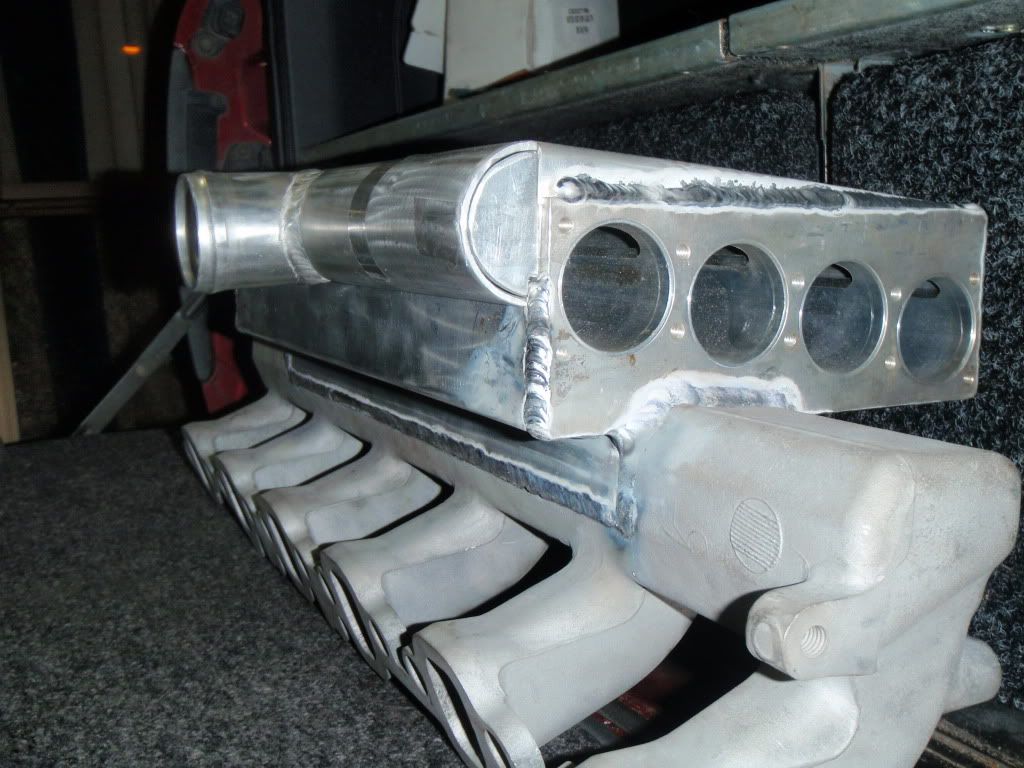
ok well got the rest of the ally bent up today for the cooler and is starting to take shape. and the sheetmetal guy did a good job bending it up. espically the bit below the cooler to fill in the manifold.
cooler welded to manifold
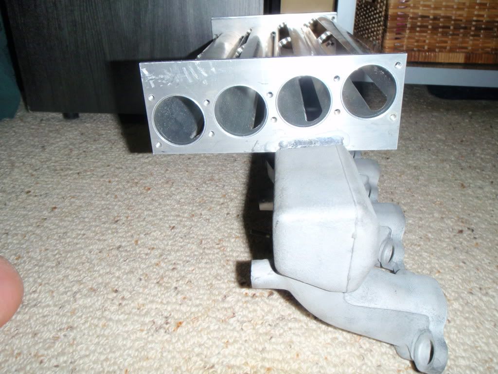
cooler welded to manifold
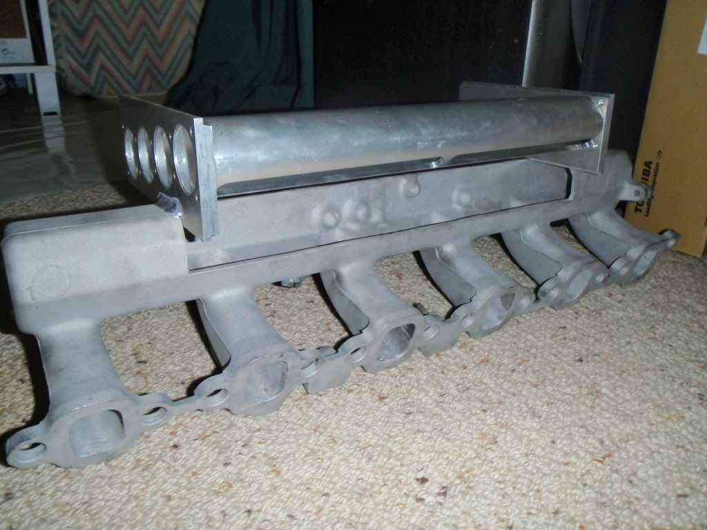
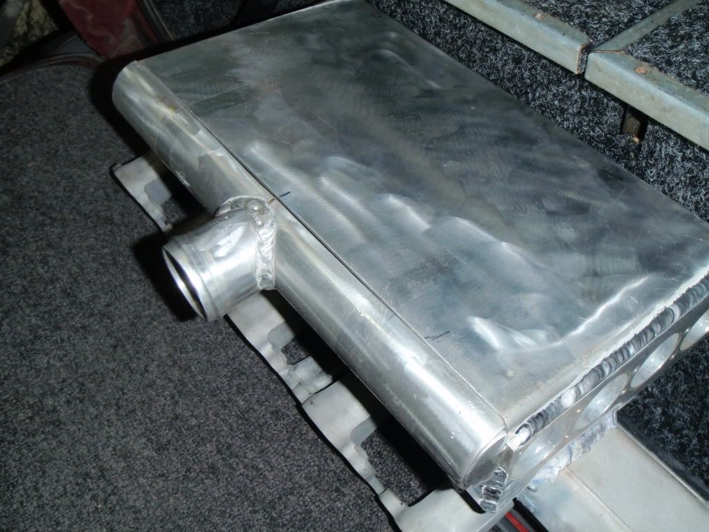
top plate so air from turbo can access the cooler
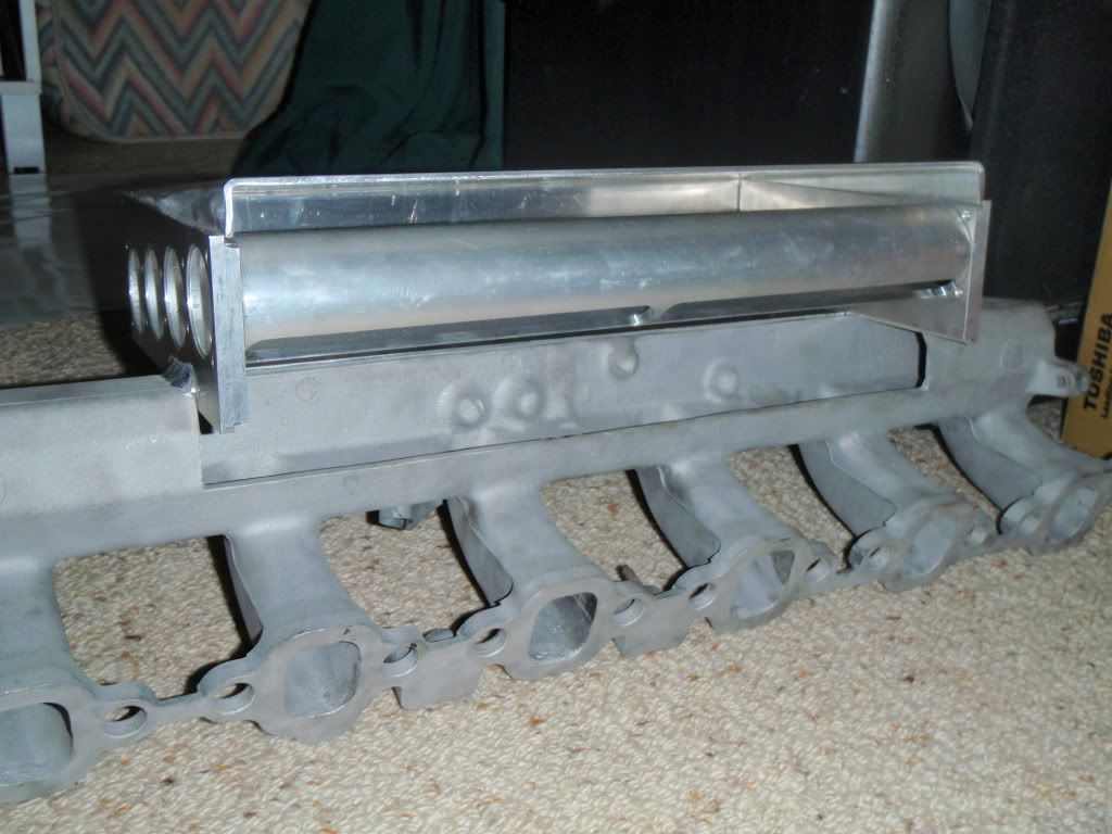
side view of top plate
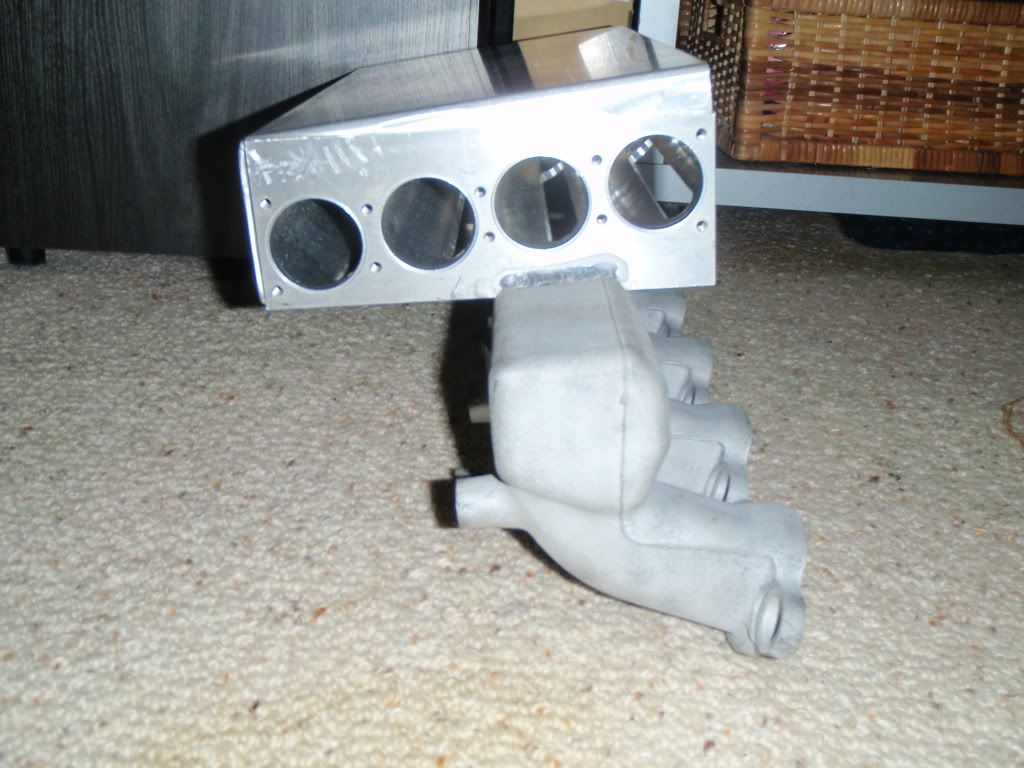
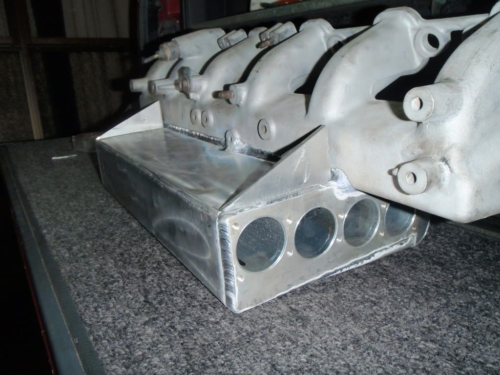
lower manifold infill piece
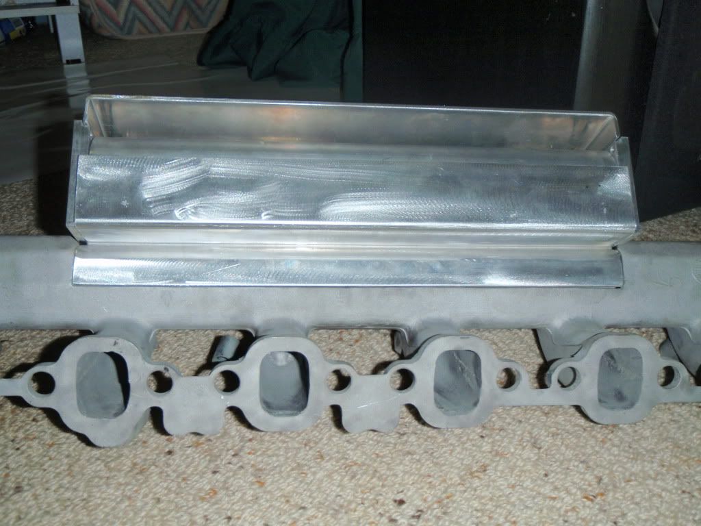
plenum in postion
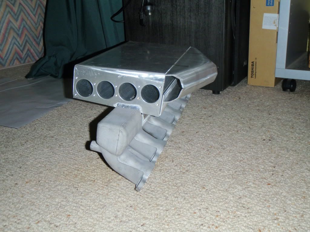
plenum in postion
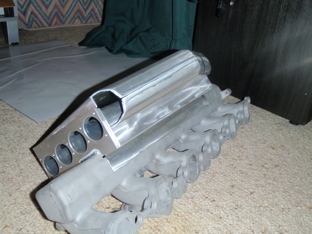
the plenum still needs to be modified i still need to take bout 10mm out of the hight and will need to take some off where the plenum touches the cooler so the plenum doesn't cover the rocker cover.
Posted: Thu Mar 25, 2010 10:29 pm
by Z()LTAN
Looks good mate.
Yeah having the cooler cover the rocker cover is damn stooid

Posted: Fri Mar 26, 2010 7:29 pm
by 80's_delirious
looking good.
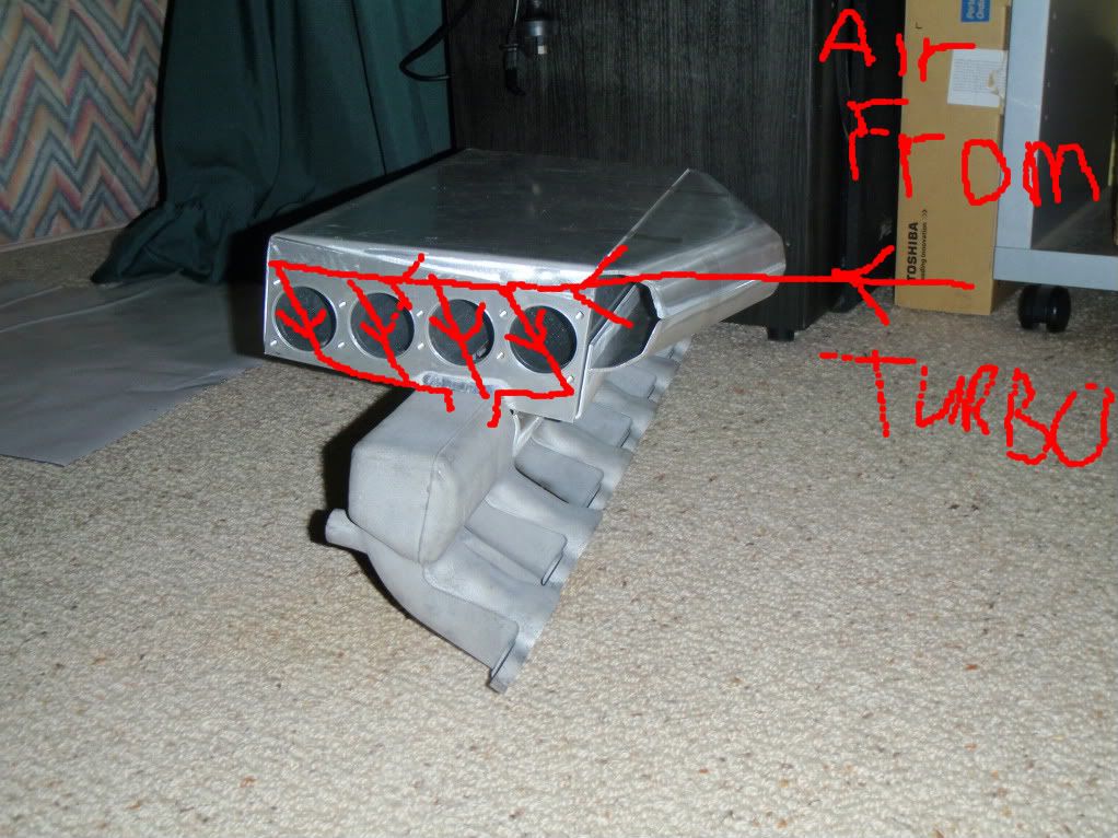
one question, should the cooler body be turned 180 degrees (turned around, not turned over) so that the slots in the tubes are arranged so that the air flow goes from the turbo, gentle angle into the tube, then out the bottom. Thee way you have it, the plenum will need to fill up, the air charge will need to turn sharply into the cooler tubes.
1st pic above, looks like the natural air flow path would be best from left to right through the cooler tubes, which is backwards to what you will actually have?
are you going to be able to hook up injectors?
Posted: Fri Mar 26, 2010 8:01 pm
by ledgend80
ok thought about that for a while but the problem is that when you get to core 3 and 4 if they where turned like you say yes the air flow from the turbo through the cores would be nice but then the air flow into the manifold would be a problem as there is not much room for the air between the core and the ally cover. and i figured that i would rather the air from the turbo fill up the plenum and all the space above the cores and then get directed nicely into the manifold. and because it is pressurised i didn't think this would be much of an issue. as the manifold sits now with the cooler mounted the cooler only sticks out 35mm from the manifold allowing you access to the injectors. and when the plenum is attached it will be up that bit higher that you can still get a spanner onto number 3 and 4 injectors.
also if you turn the body around you can't weld the cooler to the manifold because your end caps run so close to the edge. but if i wanted i can still spin the tubes around so that they were going from right to left as you say.
any way to late now as it is welded but thanks for the ideas.
Posted: Fri Mar 26, 2010 10:42 pm
by GO79
Z()LTAN wrote:Looks good mate.
Yeah having the cooler cover the rocker cover is damn stooid

i think you have started a new 1hz intake chop and weld intercooler scene mate
good stuff
Posted: Fri Mar 26, 2010 11:08 pm
by Z()LTAN
hehe someone had to do it!
Legend80, Flow paths are not too much of a problem in a pressurized system. Open flow pats will give better power/torque when the engine is not under boost.
The way you have it at the moment looks good. I will also force the air to flow through all the cores evenly.
Posted: Sat Mar 27, 2010 10:21 am
by 80's_delirious
ledgend80 wrote:ok thought about that for a while but the problem is that when you get to core 3 and 4 if they where turned like you say yes the air flow from the turbo through the cores would be nice but then the air flow into the manifold would be a problem as there is not much room for the air between the core and the ally cover. and i figured that i would rather the air from the turbo fill up the plenum and all the space above the cores and then get directed nicely into the manifold. and because it is pressurised i didn't think this would be much of an issue. as the manifold sits now with the cooler mounted the cooler only sticks out 35mm from the manifold allowing you access to the injectors. and when the plenum is attached it will be up that bit higher that you can still get a spanner onto number 3 and 4 injectors.
also if you turn the body around you can't weld the cooler to the manifold because your end caps run so close to the edge. but if i wanted i can still spin the tubes around so that they were going from right to left as you say.
any way to late now as it is welded but thanks for the ideas.
fairy muff,
there is always going to be some sort of compromise unless you go all out custom made from scratch I guess. I agree with Zoltan, turbo pressure will make air path less critical then in a naturally aspirated system.
will be good to see your finished results
Posted: Mon Apr 05, 2010 7:25 am
by Dane
Looking good mate.
Am I missing something about playing with injectors and lines? It seems to be a priority for you to be able to access these components easily. I would have thought that they are rarely required to be worked on. Same goes for the valve train. On the rare occasion (as I would imagine it) that you would need to access injector lines or remove the rocker cover, removing the intercooler to do so would not be a big deal. What sort of intervals would you need to get at these components? 40, 60 thousand kilometres? I would have imagined that the extra work in removing the intercooler on these occasions would be justified by having the intercooler mounted to maximise flow and mounting location.
Watching this thread with interest as I am planning on putting a 1HD-FTE in my 80 series and intercooling it with a similar setup.
Posted: Mon Apr 05, 2010 9:33 am
by 80's_delirious
Dane wrote:Looking good mate.
Am I missing something about playing with injectors and lines? It seems to be a priority for you to be able to access these components easily. I would have thought that they are rarely required to be worked on. Same goes for the valve train. On the rare occasion (as I would imagine it) that you would need to access injector lines or remove the rocker cover, removing the intercooler to do so would not be a big deal. What sort of intervals would you need to get at these components? 40, 60 thousand kilometres? I would have imagined that the extra work in removing the intercooler on these occasions would be justified by having the intercooler mounted to maximise flow and mounting location.
Watching this thread with interest as I am planning on putting a 1HD-FTE in my 80 series and intercooling it with a similar setup.
to remove replace the intake manifold, you need to disconnect and remove injector lines as they pass through the manifold, so it will be necessary to access them to install this manifold and do up the injector lines after it is fitted.
Legend80 looks like he has come up with a good set up, I can see some swearing going on connecting injectors again, its a bit fiddly with stock manifold

Posted: Mon Apr 05, 2010 10:39 am
by Z()LTAN
Dont forget the glow plugs, youll need to get to those when you roll it

Posted: Mon Apr 05, 2010 12:48 pm
by Dane
Cheers mate.
Posted: Tue Apr 06, 2010 9:45 pm
by ledgend80
ok just thought i would put a bit of a pic up of the air flow through the cooler for those trying to work it out.
Posted: Sun May 16, 2010 8:35 pm
by ledgend80
Posted: Sun May 16, 2010 8:42 pm
by TheBigBoy
Weld em on. You probably dont need them as it would hold that much water on the overhang anyway. But you can never have too much support. For the sake of a few stiches id do it.
Ps. Looking sh$t hot mate....
Posted: Sun May 16, 2010 10:00 pm
by Z()LTAN
Looks awesome mate!
Probably doesn't need the gussets but like bigboy said, you've got them there just whack em on.
Posted: Sun May 23, 2010 8:49 pm
by ledgend80
ok so the cooler is fully welded and now just needs to be pressure tested
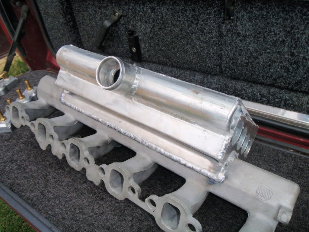
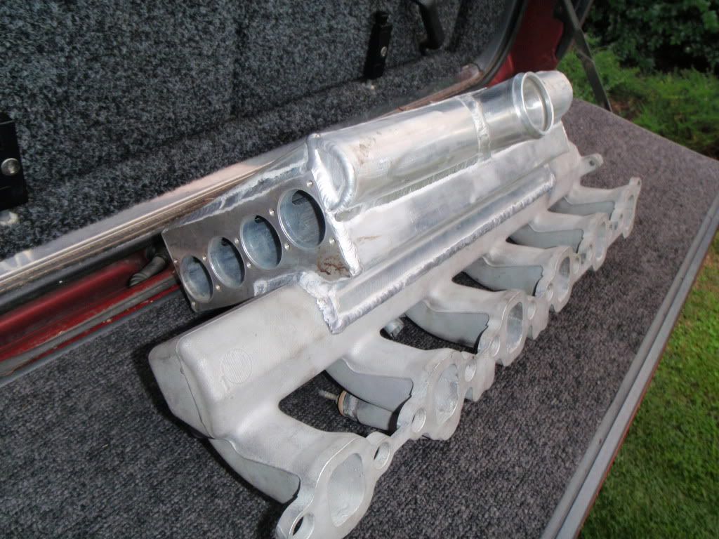
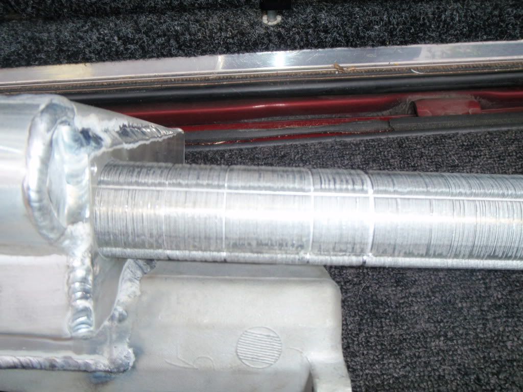
bit of an internal view
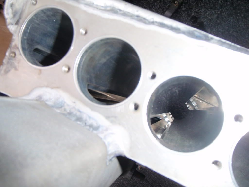
showing the core going into the cooler
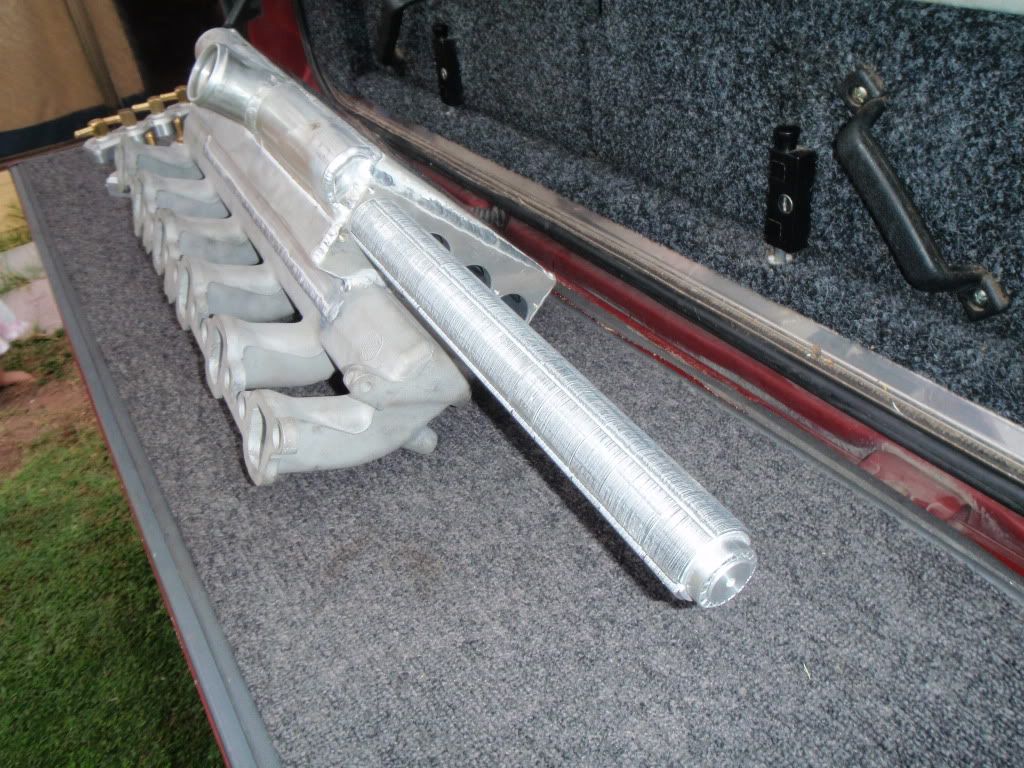
close up of the core
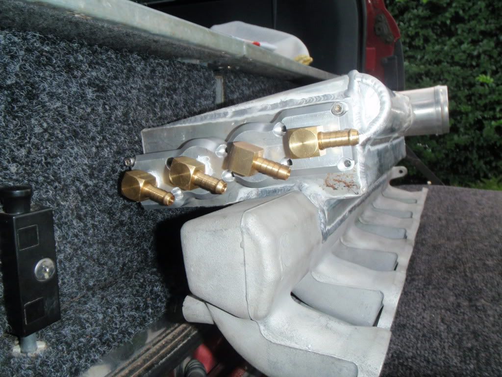
end caps with fittings
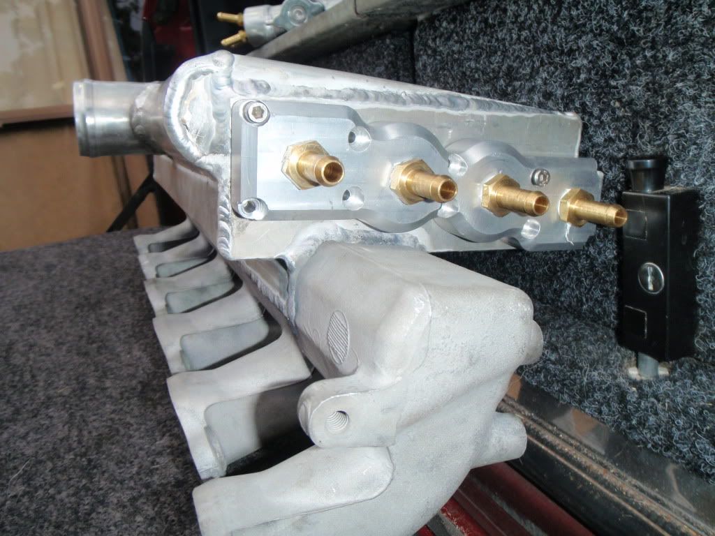
the back 2 fittings will have to be turned up away from the manifold as the hoses will hit the manifold
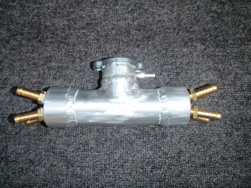
upper filler point
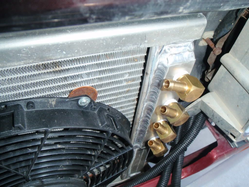
changed the r/h water inlet to what you see because i couldnt get the grill to go back on
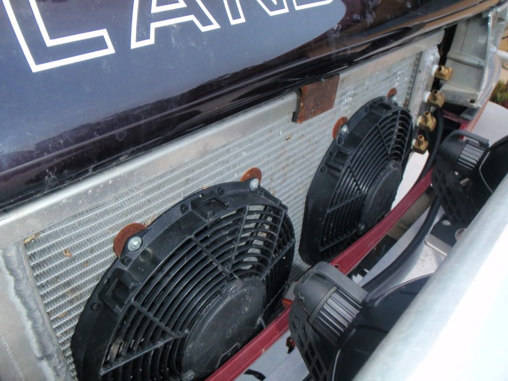
had to move the right hand fan down to be level withthe left hand one so when i run the hoses i can fit the grill
Posted: Sun May 23, 2010 9:20 pm
by Z()LTAN
sweet not long now mate!
Re: 1hdt laminova intercooler
Posted: Mon Sep 13, 2010 6:31 pm
by matt.mcinnes
BUMP

Re: 1hdt laminova intercooler
Posted: Wed Sep 15, 2010 9:08 pm
by vSAHARAx
Bump Bump.......... I bit the bullet and bought a Safari

........ top stuff on your effort mate, looks soooo much better!!! Well done mate top job!
Troy
Re: 1hdt laminova intercooler
Posted: Wed Sep 15, 2010 10:18 pm
by thrashlux
good to see a water to air done properly
those denco ones are dinky toys

Re: 1hdt laminova intercooler
Posted: Tue Feb 01, 2011 7:29 am
by TheBigBoy
BUMP. Whats happening with this intercooler? Is it done fitted and dyno/temp results yet?
Re: 1hdt laminova intercooler
Posted: Tue Feb 01, 2011 9:48 pm
by ledgend80
when i get some time i am going to start on version 2. only problem is i don't seem to have much spare time at the moment.
Re: 1hdt laminova intercooler
Posted: Tue Feb 01, 2011 11:32 pm
by 80's_delirious
did you get this version operational?
what would you change if you do another one?
Re: 1hdt laminova intercooler
Posted: Wed Feb 02, 2011 9:07 pm
by ledgend80
all i will say is pin holes f##cking pin holes that never go away.
one thing is i want is the accelarator cable to stay where it is.
Re: 1hdt laminova intercooler
Posted: Wed Feb 02, 2011 9:53 pm
by 80's_delirious
sounds frustrating

hope you get it sorted. I would love to hear what you think of the results

Re: 1hdt laminova intercooler
Posted: Wed Feb 02, 2011 10:00 pm
by ledgend80
yeah it is. gotta wait for the engineer at work to get back from perth as he has my intake manifold.


