Home brew duals adapter
Posted: Tue Apr 14, 2009 9:13 pm
I thought I might stick up a little post about what ive been up to over the last week. It started off with buying a gbox and transfer off the net for $20 8) ....
Then I got the idea of dual transfers. Since I dont have any money I couldn't buy one, and since I have access to a great workshop, I decided to make one instead
First off we start with the housing that goes between the Gbox and transfercase. The idea was to remove the flange and then mill it down flat. So out came the 9" and the mill
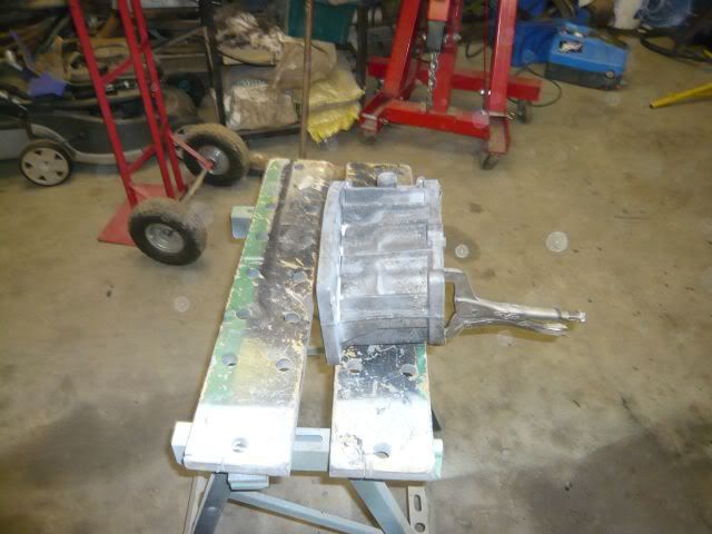
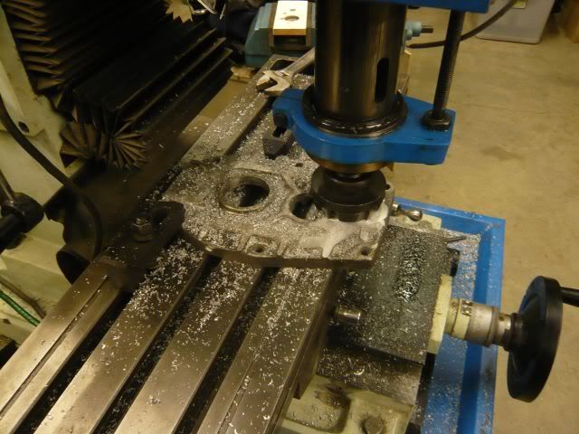
After milling it flat I started work on the output shaft.
This is the standard output shaft
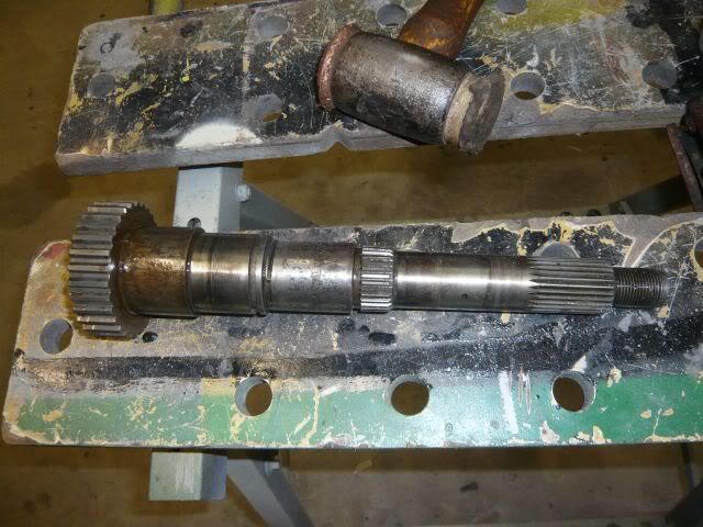
Then I cut it where it steps down next to where the circlip is to hold the bearing on it
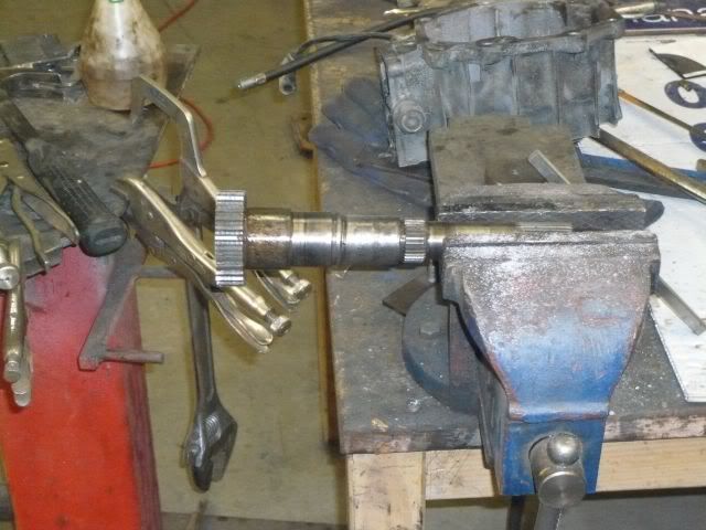
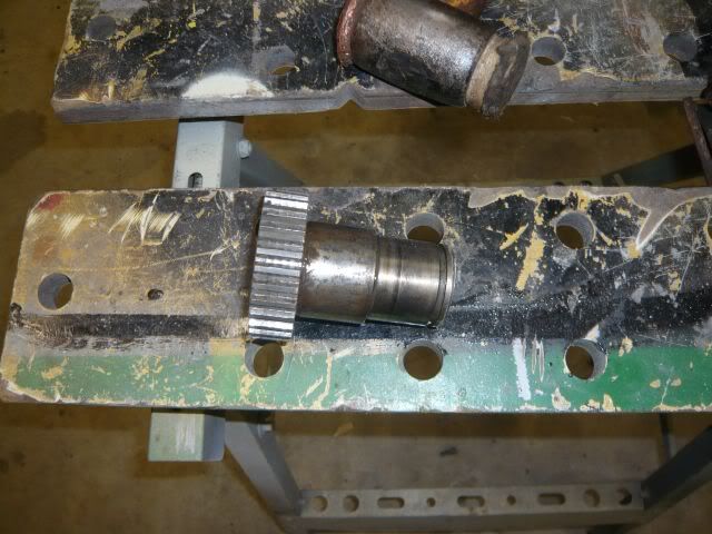
And then stuck it in the lathe and bored out the inside of it. I bored it to 34mm
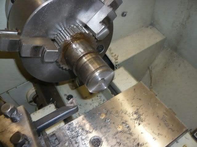
And then I took the standard coupler that goes between the gbox and xfer. This gets turned down to a press fit inside the outputshaft (I turned a little extra by accident, but it doesn't matter too much). Not shown in the chamfer I put in to assist penetration whilst welding.
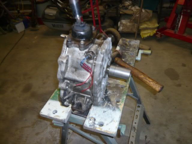
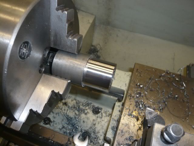
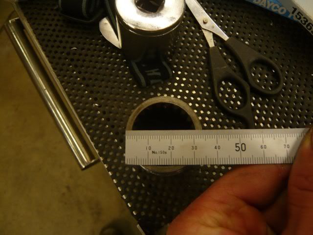
Here they are next to eachother
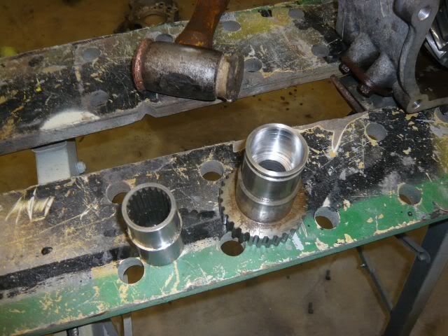
Next up it was time to start work on the 2nd flange used in my adapter. It is cut from the rear housing of the xfer and bolts on to the back of them.
I used the same technique of cutting with the 9" and then milling flat (you cannot mill the whole thing flat though). Remember first though to cut off the front output part (I used the plasma).
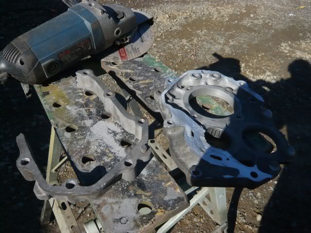
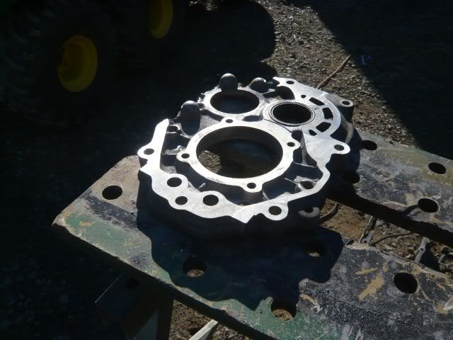
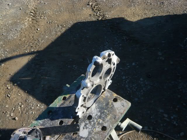
Next up I welded up the output shaft. I wanted to plug weld it but there was no way a drill bit was going through that hardened steel, so I used a 3mm cutting disc and cut 2 slots about 1" long each and welded through, and then turned it back down so the bearing and gears can pass over the top.
The bearing surface needs to be completely flat. Also at this stage harden to your liking.
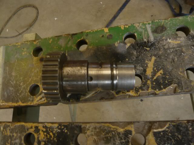
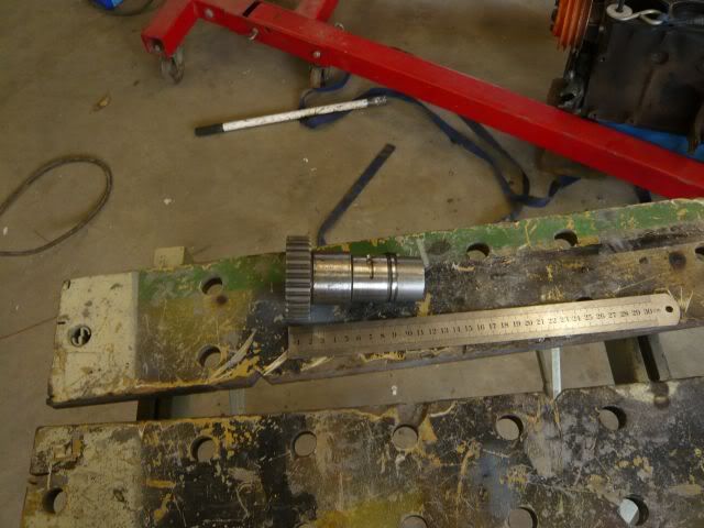
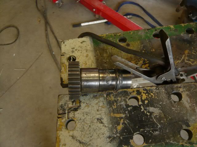
Next up it was time to start measuring. I ended up cutting a tad off the coupler to get it a bit shorter. Note it is possible to get it much shorter than I have done, but I have decided to leave it the length I have for a few reasons I won't go into. I ended up using some 50x6mm strap between the 2 flanges.
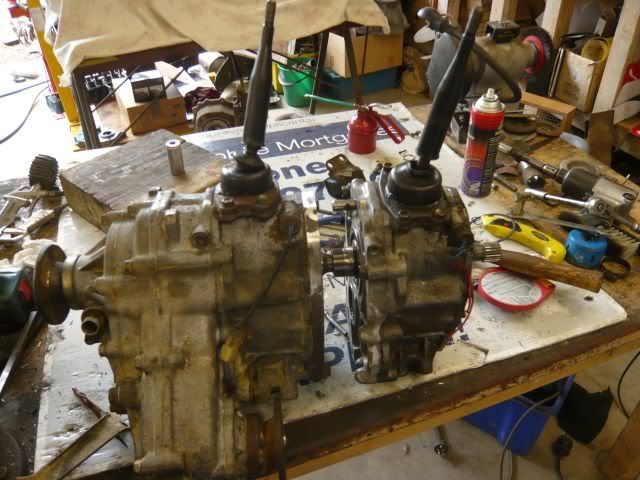
Then I stood it on its nose and used various bits of 50mm strap around it and tacked some bits in place.
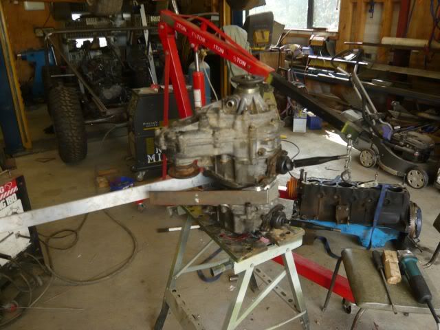
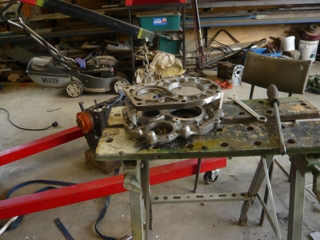
And then started filling in the gaps with more
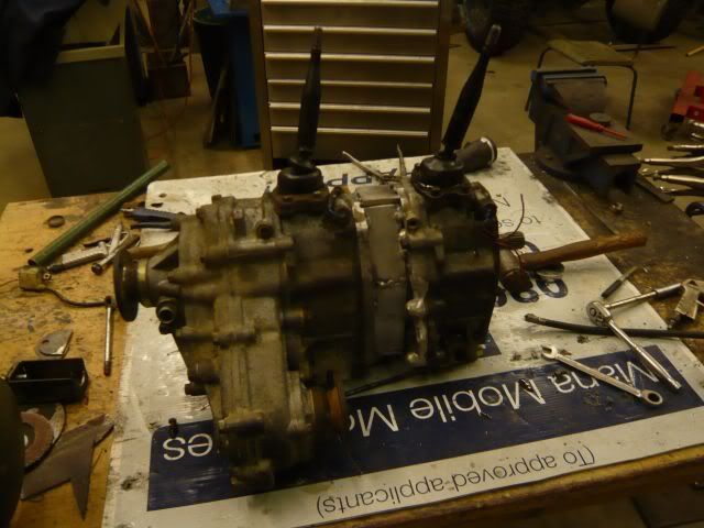
This is rough guide on how I have done my duals adapter. Its not pretty but it works well and it was cheap. I thought it was a damn good bit of engineering for a 17year old
There are no finished pics yet as it is away getting welded (I am not competent enough on a tig to do more than tack). I did forget to mention though that I clocked it 10deg at the same time.
Let me know what you think
Then I got the idea of dual transfers. Since I dont have any money I couldn't buy one, and since I have access to a great workshop, I decided to make one instead
First off we start with the housing that goes between the Gbox and transfercase. The idea was to remove the flange and then mill it down flat. So out came the 9" and the mill


After milling it flat I started work on the output shaft.
This is the standard output shaft

Then I cut it where it steps down next to where the circlip is to hold the bearing on it


And then stuck it in the lathe and bored out the inside of it. I bored it to 34mm

And then I took the standard coupler that goes between the gbox and xfer. This gets turned down to a press fit inside the outputshaft (I turned a little extra by accident, but it doesn't matter too much). Not shown in the chamfer I put in to assist penetration whilst welding.


Here they are next to eachother

Next up it was time to start work on the 2nd flange used in my adapter. It is cut from the rear housing of the xfer and bolts on to the back of them.
I used the same technique of cutting with the 9" and then milling flat (you cannot mill the whole thing flat though). Remember first though to cut off the front output part (I used the plasma).


Next up I welded up the output shaft. I wanted to plug weld it but there was no way a drill bit was going through that hardened steel, so I used a 3mm cutting disc and cut 2 slots about 1" long each and welded through, and then turned it back down so the bearing and gears can pass over the top.
The bearing surface needs to be completely flat. Also at this stage harden to your liking.


Next up it was time to start measuring. I ended up cutting a tad off the coupler to get it a bit shorter. Note it is possible to get it much shorter than I have done, but I have decided to leave it the length I have for a few reasons I won't go into. I ended up using some 50x6mm strap between the 2 flanges.

Then I stood it on its nose and used various bits of 50mm strap around it and tacked some bits in place.


And then started filling in the gaps with more

This is rough guide on how I have done my duals adapter. Its not pretty but it works well and it was cheap. I thought it was a damn good bit of engineering for a 17year old
There are no finished pics yet as it is away getting welded (I am not competent enough on a tig to do more than tack). I did forget to mention though that I clocked it 10deg at the same time.
Let me know what you think