Page 1 of 1
highmount help needed
Posted: Sat Feb 20, 2010 12:04 pm
by GQuick
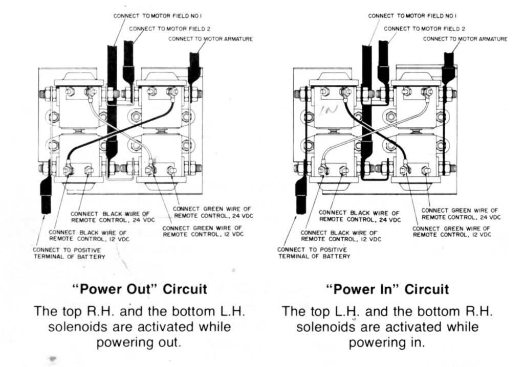
im hoping anyone can post a pic of their old 4 pin 8274 control box as the one i got is in bad shape ...dunno where any wiring goes, need to know where the solenoids wire together, control plug wires go and as stupid as it sounds, where 12v + and - go. it has the old can style solenoids and im lost

any help would be appreciated. thanks

Posted: Mon Mar 01, 2010 11:35 pm
by Leeroy
Mate I have no idea how to post pics and drawings, I can only describe this in words but I'll have a go, hope it makes sense.
Ok there should be a copper bus bar between the top left and bottom left, between the top right and bottom right, and in the middle between the two tops and another between the two bottoms.
The main battery power goes to the far left bus bar (ie outside of each left solenoids).
The armature wire goes to the bus bar on the far right (ie one of the two outside right terminals on rhs sols).
The big wire from F2 on the motor goes to the top centre bus bar (ie one of the inside terminals on the top two solenoids).
The big wire from F1 goes to lower centre bus bar (inside terminals bottom two solenoids).
Ok from memory the old solenoids like this earth themselves through their base mount on the solenoid plate, so make sure this has a good earth and is all cleans.
You need to connect the wires from the remote (white, green and brown if memory serves) to one of the small pins on each solenoid. If unsure which one you may have to use an alligator clip wire to check them and see which one makes the solenoid click (with other end of wire with clips on +ve battery).
Ok white is power, so goes on same solenoid post as you put main power feed on to, ie far left.
Green is IN circuit, and goes to pin on TOP LEFT and BOTTOM RIGHT solenoids, when operated this supplies power to F2, and connects armature to F1.
Brown is OUT circuit, and goes to pin on TOP RIGHT and BOTTOM LEFT solenoids. When operated this supplies power to F1 and connects armature to F2, reversing motor and winching out.
Whether winching in or out, you only operate two solenoids and a time, the diagonally oposite ones.
Main difference on the later ones is extra two wires in remote, red goes to earth and black goes to other pin on newer solenoids to earth them. This is so the remote powers AND earths the solenoids, to make it harder for knobjockeys to flatten your car via your towbar and a paperclip.
I hope that all made sense for you and helps out.
Oh PS, the main earth goes from the bolt in the motor (unless it's REALLY old) direct to battery earth, unless you have a colehersey type rotary manual dual battery seperator, in which case earth it to wherever you earthed the common (usually engine).
Posted: Fri Mar 05, 2010 5:33 pm
by David_S
Here's the diagram from the Warn manual

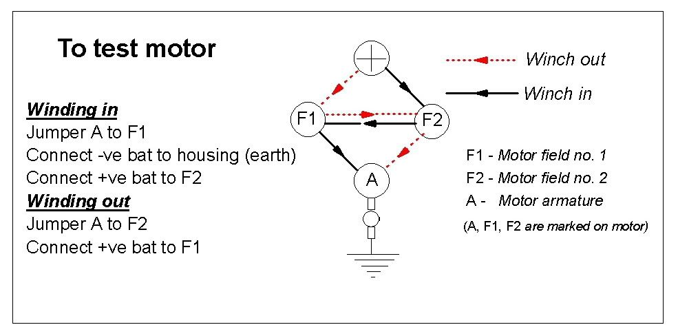
And here is how to test motor with jumpers

David
 any help would be appreciated. thanks

