Page 1 of 1
wiring 12v solenoid/D.c.v
Posted: Fri May 28, 2010 10:07 pm
by joshy
Hey guys,
I'm about to wire up the hydraulics on my truck.
Now there is no wiring diagram on how to wire up the solenoid valves.
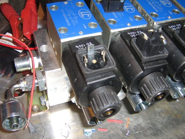
They have 3 contacts.
One is marked with EARTH and the others are marked with "1" and "2".
Which terminal is the power supply and which one is the control circuit (switching)?
I have measured them for continuity but I'm getting a circuit between 1 and 2 but not between any of them and earth?
Maybe it's not switched like a normal "relay"?
I'd appreciate some advice.
Cheers
Posted: Fri May 28, 2010 10:16 pm
by ricky1970
Ignore the centre one (marked earth) and use the two matching ones on the side for + and -.
Posted: Fri May 28, 2010 10:20 pm
by PacMan
Pin 1 and 2 is your coil.
You connect on one of the pins to the switch wire and on the other pin to the earth. No matter what way.
Do not connect any on the pin maked as earth. Not even an earth.
I can not remember what pin earth was for.
Chris
Posted: Fri May 28, 2010 10:30 pm
by ricky1970
PacMan wrote:Pin 1 and 2 is your coil.
I can not remember what pin earth was for.
Chris
The 3 pin DIN plug is common for both DC and AC use. Earth pin may be used for AC stuff. I always get a sparky when playing with AC gear so not too sure.
Posted: Fri May 28, 2010 10:31 pm
by joshy
So would that mean I don't have a "low current" input to switch?
I'd have to run a relay then to control each solenoid?
My switch wires can are only meant to run low current which is obviously not going to be used as the main power at the somenoids?
Posted: Fri May 28, 2010 10:44 pm
by ricky1970
The coils shouldn't draw that much currant. They are maybe 18 or 20 watt so relays arn't really required.
Also, dosn't hurt to give the plugs a good spray with something like Lanotec to stop corrosion of the terminals before its all tightened down.
Posted: Fri May 28, 2010 11:43 pm
by joshy
ricky1970 wrote:PacMan wrote:Pin 1 and 2 is your coil.
I can not remember what pin earth was for.
Chris
The 3 pin DIN plug is common for both DC and AC use. Earth pin may be used for AC stuff. I always get a sparky when playing with AC gear so not too sure.
The AC theory makes sense. That would explain the 3 pins with the earth.
So can anyone tell me how much current those coils will draw when activated? I don't want to burn out my wiring as the switch wires really are rather thin......
If I have to, I'll just run them through relays..... which means I'd need to have 9 additional relays

Posted: Fri May 28, 2010 11:59 pm
by ricky1970
Shouldn't be more than a couple of amps, 3 at the outside. Could check for sure when i go back to work on monday.
We use these solenoid valves quite a bit and only run through relays if needed for control issues rather than to handle high currant draw.
How thin is the wiring?
Posted: Sat May 29, 2010 2:15 pm
by joshy
Thanks mate, its pretty thin 1mm or something. i think weve worked something out now.
Posted: Sun May 30, 2010 7:34 pm
by A.J.
It's all working now guys thanks for your help!
It worked disregarding the "earth" and using 1+2 for negative and positive.
Wire seems good. Works fine
