Notice: We request that you don't just set up a new account at this time if you are a previous user.
If you used to be one of our moderators, please feel free to reach out to Chris via the facebook Outerlimits4x4 group and he will get you set back up with access should he need you.
Recovery:If you cannot access your old email address and don't remember your password, please click here to log a change of email address so you can do a password reset.

Rover 3.5 EFI conversion

Tech Talk for Rover owners.

Moderator: Micka

Posts: 19062
Joined: Sat Oct 25, 2003 11:39 pm
Location: In a horse near you

Rover 3.5 EFI conversion

Post by chimpboy »

Picked some EFI gear up this morning, going to get cracking on installing it today, to replace the carby (which doesn't seem to be working too well.)

I've got the hotwire AFM, manifold, injectors, ECU, loom, etc. Also have an EFI fuel pump from a Commodore that I got free..

I am just starting this thread now because I know I'll be needing advice soon :)
This is not legal advice.
Posts: 3385
Joined: Fri Sep 17, 2004 8:26 pm
Location: Melbourne

Post by shakes »

hope it all works out for ya! :cool:

I'd also run a surge tank, and pressure reg.

look at the commodore TB, dizzy and computer swap (think fuel rail and injectors but depends on your motor size) as I said before tuning and diagnostics will become alot easier, and your engine bay will be a lil neater.

the haynes manual for disco's has some good wiring diagrams to help ya sort out all that spaghetti, be a good couple of nights with can in one hand, manual in the other and the loom on ya lap :?

Simon
Posts: 19062
Joined: Sat Oct 25, 2003 11:39 pm
Location: In a horse near you

Post by chimpboy »

Thanks! At this point my plan is to try to get a rough-and-ready version running, basically running hoses and wires outside the car or wherever just to make sure it actually all hooks up okay.

Then once that's sorted, I'll add a surge tank and route everything neatly. That's my theory anyway.

First obvious issue is that the heater hose setup is different on the two manifolds; the old one (82 Range Rover motor) has an extra hole compared to the new one.

So that is my first mental challenge.

But EFI has to be an improvement over carby in the long run.
This is not legal advice.
Posts: 1575
Joined: Thu Dec 28, 2006 6:50 pm
Location: Moronfield....

Post by nottie »

Shouldnt have to run a presure regulater as there is one on the back of the efi manifold set up. :lol: Just dont break it as they are about $130 of hand i think.
Posts: 19062
Joined: Sat Oct 25, 2003 11:39 pm
Location: In a horse near you

Post by chimpboy »

Can anyone describe for me the coolant circuit for the heater on a 91ish Disco?

The old range rover motor setup had the heater water returning into the back of the air manifold, but the new disco manifold only has a bit of coolant system action at the front, nothing at the back.
This is not legal advice.
Posts: 19062
Joined: Sat Oct 25, 2003 11:39 pm
Location: In a horse near you

Post by chimpboy »

Also - and I realise this is a big ask - if anyone's got any of the ECU wiring diagram scanned I'd love to see it!

I realise I can buy a manual, just trying to work faster and cheaper :)

EDIT: I really only need to identify a really small number of wires, so if anyone's got that page of the wiring diagram and can scan it for me I'd be grateful.

It's a nine-pin plug and a single-pin plug off the ECU loom.

The single pin wire is orange.

The nine pin wires are:

Brown (big, I assume unfused power)
White
White with green stripe
Black with white stripe
White with purple stripe
Brown with blue stripe
Black with grey stripe
Yellow
Yellow with black stripe

I assume I am not going to need all ten of these but I guess I need to know what they all are!

Anyone? Pleease?
This is not legal advice.
Posts: 369
Joined: Tue Sep 06, 2005 6:16 pm
Location: Melbourne

Post by RangingRover »

your manifold is probably the sort which had the heater hoses coming out near the front, then running through pipes along the top of the RH rocker cover.

As for your wiring, I can give you a few hints, as the colours are pretty consistent to earlier injection also.

Brown - big fat one is constant power, from memory.
white - ign power? - not 100%
white/green - ign power, feeds into a power relay or something bizarre in your loom.
White/Purple - fuel pump power out. This colour every rangie/disco owner should know :P

the others I'm not sure of, off the top of my head.
84 Rangie, 3 inch spring lift, 2 inch body, Megasquirted 4.6, R380, rear Maxi, 34x11.5 JT2s. Simex FM installed.
Posts: 1575
Joined: Thu Dec 28, 2006 6:50 pm
Location: Moronfield....

Post by nottie »

Try searching as Ruff posted up a while ago the colours of certain cables for there intended use.
Posts: 1575
Joined: Thu Dec 28, 2006 6:50 pm
Location: Moronfield....

Post by nottie »

http://carl.outerlimits4x4.com/viewtopi ... highlight=

Found it :armsup: some good info in there plus other links for wiring.
Last edited by nottie on Thu Feb 22, 2007 12:55 pm, edited 1 time in total.
Posts: 16934
Joined: Sun Oct 20, 2002 6:57 pm

Post by RUFF »

nottie wrote:Try searching as Ruff posted up a while ago the colours of certain cables for there intended use.
Yep search for a post by me about wiring or EFI in this section. Everything you need to know is in that thread its a very simple efi to wire up.
Posts: 19062
Joined: Sat Oct 25, 2003 11:39 pm
Location: In a horse near you

Post by chimpboy »

Thanks a lot guys, I really appreciate it... saves me the cost of a manual I don't really need.

I have just been out getting some steel tube to run the fuel through, as it goes pretty close to the exhaust I wasn't comfortable running high pressure fuel through rubber hose only.

So fingers crossed when I've got the physical side of it all hooked up, I should be able to wire it as suggested in the thread nottie posted and fire it up!

I farking hope so, anyway!

:)

Jason
This is not legal advice.
Posts: 19062
Joined: Sat Oct 25, 2003 11:39 pm
Location: In a horse near you

Post by chimpboy »

ruff wrote:I just fitted an early disco 3.5 EFI kit to my hilux. This is slightly different in the wireing on the 3.9 but is prob the same to wire.

I only had to hook up 3 wires to get this to run.

Brown wire- Battery +
White with a Red Trace- Ignition Sorce
White with Purple Trace to Fuel Pump +

There is also a White with a Yellow trace that is the Check engine light but i havent added this yet.

And it runs perfect.
ruff wrote:Ok i have another style of wiring to get them to run other than what i posted in the link above-

Small white/purple wire-Fuel pump
Large purple/white wire-Ignition Source
Large Brown-Constant Power
These wires are all in the plug just after the harness comes through the firewall.
And White/Green to coil(This wire is usually found out near the Airflow meter wiring.

The Above wiring is what i used in my 97 Disco motor into my 86 rangie.

Just confirming, the "white/green" to coil means to the dizzy signal on the coil right?
This is not legal advice.
Posts: 19062
Joined: Sat Oct 25, 2003 11:39 pm
Location: In a horse near you

Post by chimpboy »

Actually, these colours are not quite a match for what I've got. Hrmm, I'll see how it goes with a bit of guesswork.
This is not legal advice.
Posts: 1575
Joined: Thu Dec 28, 2006 6:50 pm
Location: Moronfield....

Post by nottie »

what year vehicle did your setup come off?
Posts: 19062
Joined: Sat Oct 25, 2003 11:39 pm
Location: In a horse near you

Post by chimpboy »

nottie wrote:what year vehicle did your setup come off?
Good question. I think it was a 1991 model... Shakes?
This is not legal advice.
Posts: 3385
Joined: Fri Sep 17, 2004 8:26 pm
Location: Melbourne

Post by shakes »

1991 Discovery, 3.5L manual
Posts: 1575
Joined: Thu Dec 28, 2006 6:50 pm
Location: Moronfield....

Post by nottie »

wonder if they are the same engine harness as a 87/90 range rover?


Just go thru yours and post up your colours and ill cross reference them to my 3.5 rangie donk :idea:
Also have a 3.9 in the shed but i know they are certainly diffrent
Posts: 19062
Joined: Sat Oct 25, 2003 11:39 pm
Location: In a horse near you

Post by chimpboy »

Actually I apologise, the first quote I pasted in from Ruff matches my loom after all.

I got confused by (a) the stuff in the second quote and (b) the fact that the white/red wire is plain white on the other side of the plug!

Still haven't tried to fire it up, running proper fuel (steel) fuel lines was a dirty, cramped, bugger of a job! Bloody hard to thread those things through all the tight spaces. Worth it though, rubber hose the whole length might have been okay but I would have been constantly worrying about its condition.
This is not legal advice.
Posts: 490
Joined: Sat Oct 30, 2004 3:44 pm
Location: Sydney

Post by Philip A »

Just remember the signal wire from the coil goes to coil negative. it is what tells the injection the revs the engine is doing, and also cuts off the fuel if the engine stops.
Re heater .on a 3.9 the two heater hoses come from the back of the water pump. My 3.9 has 2 stubs on the back of the water pump.
The sucking water entry is in the middle of the pump. the other one on the relative "outside" of where the impeller is , is not used and blank.
The exit for the heater water is usually on the manifold , so there should be a hole there somewhere. If not you could tap into the water chamber at the front of the manifold.
I cannot tell you exactly where as mine has a Thor manifold, and I used the pipe exit already on it.
Regards Philip A
Posts: 19062
Joined: Sat Oct 25, 2003 11:39 pm
Location: In a horse near you

Post by chimpboy »

Yeah the heater pipe situation is a bit weird.

The old manifold had a setup that was easy to understand as far as the heater-sized hoses go.

On the front of the manifold was a water pipe that connected with a little dog leg hose to a pipe on the pump. This actually went to a "tee" on the pump, with one side of the tee going into the pump and the other side connected to the heater at the firewall.

And then the other heater pipe on the firewall was connected to another water outlet on the BACK of the manifold.

So the heater circuit was front of manifold (near thermostat) -> tee at water pump -> heater -> back of manifold.

The new manifold has no pipe on the back of the manifold. I am sure I just need to put a T somewhere but I can't decide where!

I guess if the one hose is on the pushing side of the pump, the other heater hose has to be on the pulling side? I've never really grasped this, heater hoses always seem to work by magic to me :)
This is not legal advice.
Posts: 19062
Joined: Sat Oct 25, 2003 11:39 pm
Location: In a horse near you

Post by chimpboy »

Maybe I just need to run one heater hose to the pump, and the other to the front of the manifold... hmm.

Just to clarify, is this what you are saying your arrangement is Philip?
This is not legal advice.
Posts: 19062
Joined: Sat Oct 25, 2003 11:39 pm
Location: In a horse near you

Post by chimpboy »

STARTED FIRST FARKING TURN OF THE KEY!

Compared to the carby, which took me about five minutes to start it on.

This is all just loosely connected together stuff, not permanent wiring or air filter mount etc.

But what an awesome feeling, I was pretty nervous at the prospect of troubleshooting it!

Thanks for the help.

There is one bit of wire I don't know where to connect up, it is the two-pin plug that comes out of the loom at the same place as the two earth wires. What is this for? Anyone know?

I still haven't worked out how to put the heater circuit into the cooling system. It basically doesn't add up for me - I have an odd number of connections, so I either need to block one off or add another tee somewhere.

Can anyone with a 91 disco have a look and tell me where the two heater hoses go after they leave the firewall? And, what other coolant hoses come from the air/fuel manifold and to where?

I'm so grateful for the help with this. Man, it felt good to hear that thing fire up, even if it was only for about 1 second since the cooling system was only half connected.
This is not legal advice.
Posts: 490
Joined: Sat Oct 30, 2004 3:44 pm
Location: Sydney

Post by Philip A »

Later EFIs have 2 pipes which run along the top of the right rocker cover, as LR thought at the time of introducing 3.9 (1989)That overheating was caused by airlocks.
The two pipes have a filler riser on one to top off the coolant.
Both pipes come from the FRONT of the engine.

I am sure one pipe comes out of the back of the water pump, and I think the other comes out the front of the manifold. On my Thor,the second pipe comes out the front of the manifold, but I cannot remember where it did on the 3.9 manifold. So the circuit is from manifold to heater and back to pump, as the pipe is in the centre which would be low pressure.

The two wires are probably the aircon turn on sensor so that the IACV can up the idle.
Regards Philip A
Posts: 19062
Joined: Sat Oct 25, 2003 11:39 pm
Location: In a horse near you

Post by chimpboy »

Philip A wrote:Later EFIs have 2 pipes which run along the top of the right rocker cover, as LR thought at the time of introducing 3.9 (1989)That overheating was caused by airlocks.
The two pipes have a filler riser on one to top off the coolant.
Both pipes come from the FRONT of the engine.

I am sure one pipe comes out of the back of the water pump, and I think the other comes out the front of the manifold. On my Thor,the second pipe comes out the front of the manifold, but I cannot remember where it did on the 3.9 manifold. So the circuit is from manifold to heater and back to pump, as the pipe is in the centre which would be low pressure.

The two wires are probably the aircon turn on sensor so that the IACV can up the idle.
Regards Philip A
Okay, I have those two pipes. They are rather useful actually, I think they'll make it easy to bleed the cooling system.

Is there any hose going directly between your manifold and your water pump?
This is not legal advice.
Posts: 2691
Joined: Sun Sep 03, 2006 7:31 pm
Location: where ever the track takes me

Post by muddydigger »

this is a simple drwing I know but its the 97 disco cooling. should be similar to yours. Image
For Kart racing information please visit our site at www.auskart.net
Posts: 19062
Joined: Sat Oct 25, 2003 11:39 pm
Location: In a horse near you

Post by chimpboy »

muddydigger wrote:this is a simple drwing I know but its the 97 disco cooling. should be similar to yours.
It may be a simple drawing but it's exactly what I needed.

Thanks!
This is not legal advice.
Posts: 19062
Joined: Sat Oct 25, 2003 11:39 pm
Location: In a horse near you

Post by chimpboy »

Okay, right next to the front-most injector on the passenger side, there is a 10mm (roughly) pipe sticking out of the manifold.

I assumed this was going to be vacuum or something, left it unconnected (thank goodness)... because it actually carries coolant! Tried to start the motor and coolant came jetting out of it.

Is anyone close to their motor? Muddydigger? If you could tell me where this pipe is meant to be connected... that would be a big help.

I think I am pretty close now, set up a new air filter and mounted the air flow meter unit and all.

EDIT:

It looks like the pipe next to the injector is meant to run coolant to one of two pipes directly under the throttle body. If this is correct, where does the second pipe under the throttle body go? I have quite a long hose coming off it, no obvious place to plumb it to though.
This is not legal advice.
Posts: 2691
Joined: Sun Sep 03, 2006 7:31 pm
Location: where ever the track takes me

Post by muddydigger »

As you are looking at the car under the bonnet. The plenaham chamber inlet is on the right. Under the throtal sensor is two coolant hoses. The right on is a long one that goes to the radiator next to the inlet for the expansion tank. the other one (left) goes to the top of the inlet manifold that ones about 6 inches long.the big hose directly next to the throtal scensor is an air hose and is conected to the flame cather on the left bank rocker cover. There is a T piece in that one that goes into the manifold aswell.

let us know how you go
For Kart racing information please visit our site at www.auskart.net
Posts: 19062
Joined: Sat Oct 25, 2003 11:39 pm
Location: In a horse near you

Post by chimpboy »

muddydigger wrote:As you are looking at the car under the bonnet. The plenaham chamber inlet is on the right. Under the throtal sensor is two coolant hoses. The right on is a long one that goes to the radiator next to the inlet for the expansion tank. the other one (left) goes to the top of the inlet manifold that ones about 6 inches long.the big hose directly next to the throtal scensor is an air hose and is conected to the flame cather on the left bank rocker cover. There is a T piece in that one that goes into the manifold aswell.

let us know how you go
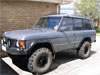
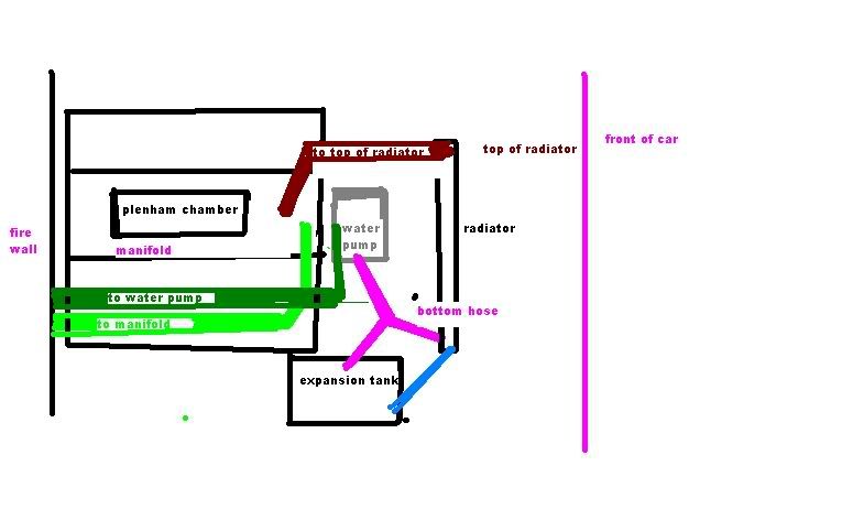
Thanks mate. Shiat, I don't have a suitable pipe on my radiator at all...

I think I should be able to run it into one of the heater hoses, I just have to work out which one. Anyone got any suggestions?
This is not legal advice.
Posts: 2691
Joined: Sun Sep 03, 2006 7:31 pm
Location: where ever the track takes me

Post by muddydigger »

Image
For Kart racing information please visit our site at www.auskart.net
Post Reply

Who is online

Users browsing this forum: No registered users and 5 guests