Notice: We request that you don't just set up a new account at this time if you are a previous user.
If you used to be one of our moderators, please feel free to reach out to Chris via the facebook Outerlimits4x4 group and he will get you set back up with access should he need you.
If you used to be one of our moderators, please feel free to reach out to Chris via the facebook Outerlimits4x4 group and he will get you set back up with access should he need you.
Recovery:If you cannot access your old email address and don't remember your password, please click here to log a change of email address so you can do a password reset.
Worklight wiring diagram?? Help please
Moderator: -Scott-
Worklight wiring diagram?? Help please
Hi all,
Wanting to install a worklight off my rear wheel carrier. Wanting to have a switch internal and also external - can this be done - what will the wiring layout be?
Foghornn
Wanting to install a worklight off my rear wheel carrier. Wanting to have a switch internal and also external - can this be done - what will the wiring layout be?
Foghornn
depending on your switches/light you may need to install a relay.
if either switch is on the light will be on. It requires both switches to be off to be off.. Only downside to this setup is if you get some little %#$ turn on the outside switch whilst you're parked somewhere you can count on a flat battery coming your way, and a copper will pull ya up if ya don't notice it.
This is a simple setup. but if you want more complex eg, outside switch only works if inside switch is on or is in a certain position (for a multi-position switch) it's easy done. just let me know.
hope this helps
Matt

2000 GU ST Patrol 4.2 turbo oiler not so bog stock anymore
"EVILGU"
"EVILGU"
Thanks guys,
Hitman, I did have concerns with the little .... turning the bloody thing on from outside so was thinking like you that a setup with the outside switch working only if the inside one is on would be good. I've setup the fridge so that the missus can just turn it on from the dash as she heads down to the shops and that was quite easy but I'm not too sure with 2 switches. I'd also like to have a relay so that theres low current into the car itself - just like with headlights etc. but am unsure of if I could just do this and then place another switch beside the actual light at the back of the car inline. Can an ordinary switch handle the load or would i need to get something special?
Sorry I should have been a bit more specific in my initial question.
Foghornn
OK, I'll presume you're talking about a 55W worklight, not a 200W aircraft landing light...foghornn wrote:Thanks guys,
Hitman, I did have concerns with the little .... turning the bloody thing on from outside so was thinking like you that a setup with the outside switch working only if the inside one is on would be good. I've setup the fridge so that the missus can just turn it on from the dash as she heads down to the shops and that was quite easy but I'm not too sure with 2 switches. I'd also like to have a relay so that theres low current into the car itself - just like with headlights etc. but am unsure of if I could just do this and then place another switch beside the actual light at the back of the car inline. Can an ordinary switch handle the load or would i need to get something special?
Sorry I should have been a bit more specific in my initial question.
Foghornn
A relay is typically used to avoid the voltage drop from running the high current into the cabin and back out again.
If you're running power from a battery in the front to a light down the back then you may not need to run the wires far out of their way to where you want the switch. If not, there's not a lot to be gained by using a relay - there are definitely switches out there capable of handling that sort of current.
Matt's circuit will work, but I'd be more inclined to put relay (switched by internal switch) in series with external switch - so light will only come on when BOTH are on. Leave the external switch on most of the time, internal switch controls when light is on/off. Around camp, internal switch is on, and use the external switch to turn the light on/off as you need it - use the internal switch to isolate the circuit day to day.
Of course, it is illegal for rear facing white lights (other than reversing lights) to be switchable from the driver's position.
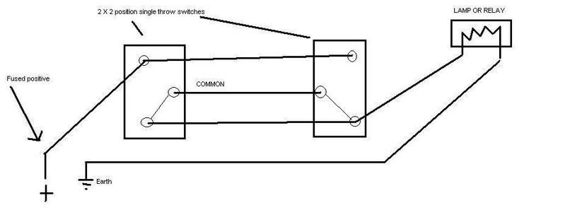
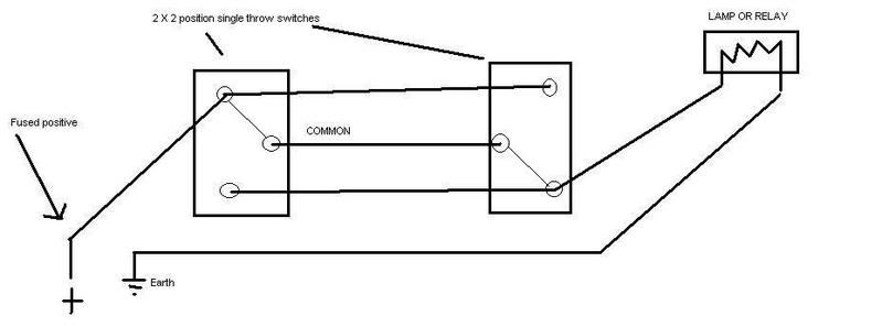
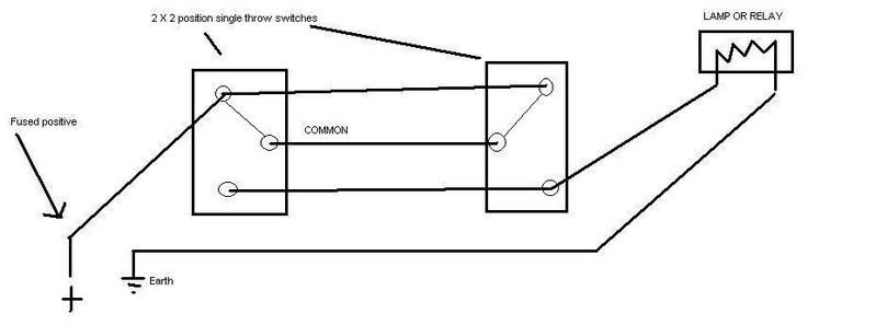
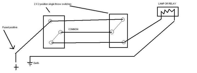
It's possible to have 2 switches that turn the lamp on or off from either, regardless of the position of either.
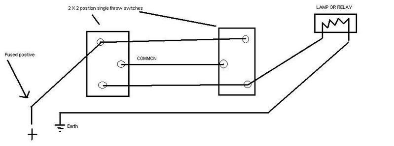
This is the way it is done in household circuits when you have a big room and want a switch in 2 locations for the 1 lamp.
If your only running a 55W lamp, then 2 X 10 amp automotive switches will do the job.

This is the way it is done in household circuits when you have a big room and want a switch in 2 locations for the 1 lamp.
If your only running a 55W lamp, then 2 X 10 amp automotive switches will do the job.
I'm the sharpest tool in the shed!
Could you throw some detail into that diagram, to show what the contacts are doing? The way I interpret that diagram, worst case, current flows between the two switches three times. Is that what you're suggesting?v6hilux wrote:It's possible to have 2 switches that turn the lamp on or off from either, regardless of the position of either.
This is the way it is done in household circuits when you have a big room and want a switch in 2 locations for the 1 lamp.
If your only running a 55W lamp, then 2 X 10 amp automotive switches will do the job.
yeah i think you need to re draw that picture with the fused active going to the common terminal on sw1 and the feed to the light attached to common terminal on sw2. the way it is drawn it will be on when sw1 is off and sw2 is on and it will be off when both are in the on position. very confusing,
swb safari
Yes, that's a worst case - why have current flow between the switches three times, when once is all that's required? What's the point in adding that much resistive loss to the circuit? Any electrician who wires like that is using excess copper, which is costing the client too much.v6hilux wrote:There is nothing "worst" about it! It's just "analogue logic"!
Try this:
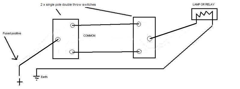
And the switches are single pole double throw - a single throw switch is only closed in one position.
Last edited by -Scott- on Sun Dec 02, 2007 8:28 am, edited 1 time in total.
It was a long day, and for me fuses go without saying, although you're right i should have put it in the diagram. I was more going for the general concept of what needed to be done for the most basic of setups.v6hilux wrote: What about a fuse to prevent the car burning to the ground?
If i were to do it myself i'd rig it up like scott has drawn most likely with a relay as i have a 4 gauge already running to the back of the car direct off the battery (via a fuse) and from there 8 gauge to the roof rack.
2000 GU ST Patrol 4.2 turbo oiler not so bog stock anymore
"EVILGU"
"EVILGU"
Of course resistance is an issue. We're talking about 12V systems, and loads which are capable of creating a significant voltage drop. You're suggesting a circuit which can send current from the front of the vehicle, to the rear, back to the front, and then back to the rear again. We normally recommend using larger cable to minimise voltage drop, and you recommend tripling up? You're a cable dealer, aren't you!v6hilux wrote:As far as resistance, thats not the issue.-Scott- wrote:Yes, that's a worst case - why have current flow between the switches three times, when once is all that's required?
I thought I did. Perhaps you missed it?v6hilux wrote:Show us how you would do a cheap circuit that allows two independent switches.
-Scott- wrote:Try this:

Last edited by -Scott- on Sun Dec 02, 2007 8:29 am, edited 1 time in total.
Scott, your interpretation of the English language astounds me. Your arrogant attitude is that of a retail trader. You are surely a legend in the workplace mealroom.-Scott- wrote:You're a cable dealer, aren't you!
I thought I did. Perhaps you missed it?
Tell me how your description of a circuit with 2 independent switches (not reliant on each other) could be better than mine without getting into a logic device to do the same thing. Did you not see the word relay in my diagrams? Tell me how critical it is when operating such a low current device that draws less current than 1 of 2 incandescent taillamps from an equal length of wire?
You are scaring people here!
There is no need. The "customers" here are not mass producing vehicles, so the extra 2 or 3 metres of wire is irrelevant to the cost when the added feature of a second switch is involved!
Also, anyone with a walk through hall or room in a house or building will be able to use this circuit to make life easier in darker times of the day.
I'm the sharpest tool in the shed!
I saw the word relay, but i also saw the words "lamp" and "or"v6hilux wrote: Did you not see the word relay in my diagrams?
running the power back and forth when it's not necessary is not good practice (just like me leaving the fuse off the diagram is not good practice). Whilst i will concede that if this was to be switching a relay, being a low current device, it really wouldn't make much operational difference, however it is messy, innefficient and should it be used to switch a lamp directly, as your diagram suggests is possible, it could result in voltage drop as the electricity would need to travel 3 times the distance.
cheers
Matt
2000 GU ST Patrol 4.2 turbo oiler not so bog stock anymore
"EVILGU"
"EVILGU"
I am not sure what you are getting at with your reference to a "logic device", but it seems to me that Scott's diagram uses less cable and complexity to achieve the same outcome as your more complicated diagram.v6hilux wrote:Tell me how your description of a circuit with 2 independent switches (not reliant on each other) could be better than mine without getting into a logic device to do the same thing.
Also, they are single-pole, double-throw switches (which Scott left wrong in his version of the diagram) in case anyone is going out shopping for this gear.
This is not legal advice.
What's with the personal attacks? Don't like being wrong?v6hilux wrote:Scott, your interpretation of the English language astounds me. Your arrogant attitude is that of a retail trader. You are surely a legend in the workplace mealroom.-Scott- wrote:You're a cable dealer, aren't you!
I thought I did. Perhaps you missed it?
I did.v6hilux wrote:Tell me how your description of a circuit with 2 independent switches (not reliant on each other) could be better than mine
v6hilux wrote:You are scaring people here!
Your circuit may work, but there's a better way to do it - and it's not just my opinion, nor is it my circuit. Stick with advising on nuts and bolts. Your electrical advice sucks.v6hilux wrote:Also, anyone with a walk through hall or room in a house or building will be able to use this circuit to make life easier in darker times of the day.
Fixed it - just for you.chimpboy wrote:Also, they are single-pole, double-throw switches (which Scott left wrong in his version of the diagram) in case anyone is going out shopping for this gear.
A logic device could a processor (module) with 1,2, 50 or any number of switch inputs that will control a lamp or relay to switch on or off.chimpboy wrote:I am not sure what you are getting at with your reference to a "logic device"
I guess I took that the wrong way.-Scott- wrote:You're a cable dealer, aren't you!
I'll take back anything you think is personal!
I don't the world to be a nasty place!
I'm the sharpest tool in the shed!
Who is online
Users browsing this forum: No registered users and 1 guest
