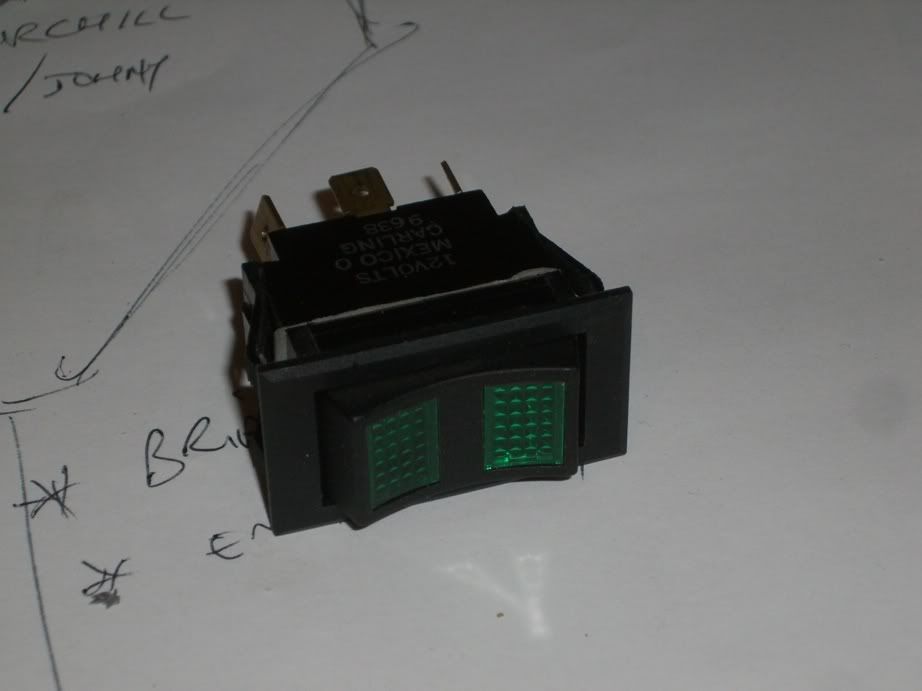
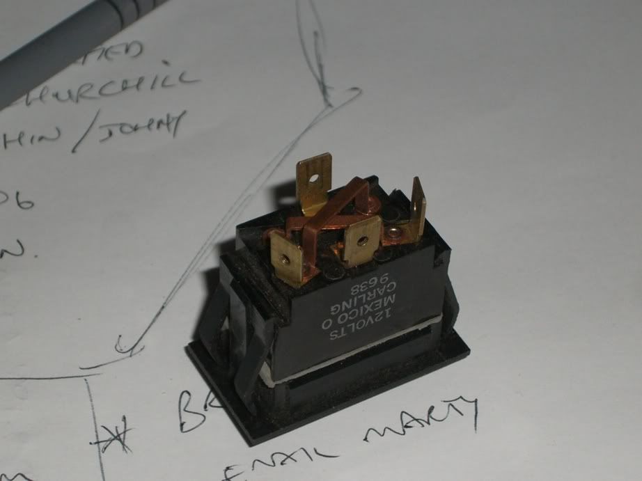
I found this switch as I prowled through my junk, and need it to use as a override on my Redarc isolater.
I like the momentary/continuous function of it, with light up bits, but I can't work it out on the multimeter...
The instructions on the Redarc call for 10amp momentary switch, but I figure this must be rated higher, and it will be able to hold the load continuously ie. batteries joined (needed to run a 1500w inverter)
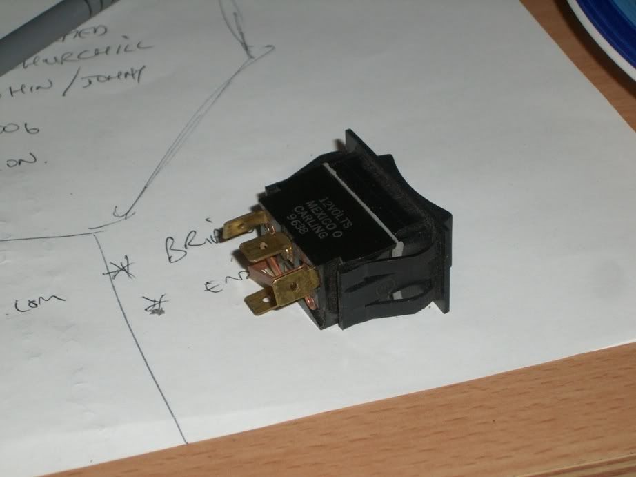
So, question is, how do I wire it up. For the redarc, I simply need a feed from the redarc, and a return to it, with a connection (switch) in between. We'll assume the current will be enough to run the LED's in the switch. Question is, what goes where??
Notice: We request that you don't just set up a new account at this time if you are a previous user.
If you used to be one of our moderators, please feel free to reach out to Chris via the facebook Outerlimits4x4 group and he will get you set back up with access should he need you.
Recovery:If you cannot access your old email address and don't remember your password, please click here to log a change of email address so you can do a password reset.
Wiring up a carling switch...
Moderator: -Scott-
Wiring up a carling switch...
'97 HDJ80 - worth the wait
Guess: two commons are the middle two pins - one +, one -.
When switch moves to either end, probably the pin at the opposite end shorts to the + common. The other centre pin would then be the - common.
If you have a diode check function on your multimeter try measuring for a diode between a cross-over bar and each of the centre pins. Both bars should indicate a diode connection to one of the centre pins, and I would expect that to be -ve - unless the switch was designed for -ve switching.
Confused? If so, my work here is done.
A diode?ash_on_mtb wrote:What does the diode testing icon on a multimeter look like??
1. Press switch one way or other. You should have a closed circuit between one of the centre pins, and one of the end pins.
2. Press switch the other way. You should have a closed circuit between the same centre pin, and the other end pin.
If not - it's got me buggered!
If so: +12 to the centre pin which created a connection, ground (-ve) to the other pin. Press the switch and you'll either get a light, or let some smoke out. (If you let the smoke out, make sure you catch it all - the switch won't work without it.) If nothing happens, you could try reversing the connections and repeat the test.
Sounds right.
Appears to have 2 lights in the switch, one at either end of the switch. Run the + in to the middle tab between the 2 other tabs (line from battery + to middle tab). Should be able to bridge the tabs on the other sides and run a wire to the redarc. Then run a line to ground from the single tab on the other side of the switch. All this tab does is to provide a ground for the lights in the switch. The crossover power bars on the back of the switch are to alternately provide + and - to the lights in the switch depending on the way the switch is pushed.
May need to reverse the above as early and late model redarcs have reversed inputs for the manual switch according to their website, so best to check which one you have. Mine is Positive at redarc - wire to switch - switch - wire to ground.
Hope this isnt too messed around.
Sam
Who is online
Users browsing this forum: No registered users and 1 guest