if building a A frame rear end, using a rover ball joint, lowers (trailing arms) are parralell to chassis, what is the minium angle the "A" can be to still locate the axle lateraly?
Serg
Notice: We request that you don't just set up a new account at this time if you are a previous user.
If you used to be one of our moderators, please feel free to reach out to Chris via the facebook Outerlimits4x4 group and he will get you set back up with access should he need you.
If you used to be one of our moderators, please feel free to reach out to Chris via the facebook Outerlimits4x4 group and he will get you set back up with access should he need you.
Recovery:If you cannot access your old email address and don't remember your password, please click here to log a change of email address so you can do a password reset.
rear link q's
Moderators: toaddog, TWISTY, V8Patrol, Moderators
just doing up some drawings for an exercise. so i can learn a bit more.
defender type rig, approx 115 inch wheelbase.
weight 2200kg
rover type axles with 5 inch drop portals running 255 85 r 16
2.5 ltr tdi
im guessing some of the reasons rover ball joints get destroyed is 1, the material the oem are made from and 2, any hard core rig with lift will have bad ball to A arm angle which will cause binding.
now as far as link length, im starting with the angle of the a arm first, this will determine my max lenght for a fixed distance between chassis rails, then i can make the trailing arms 1.2 times longer than the A arms.
link seperation at axle will be approx 260mm
Serg
I would run 125-150mm seporaton at chassis end, run the A frame legs as wide apart as is possable. The width on A frame leg seporationis so connected with the arm length.
Rough guide, 260 mm diff end will suit 37" tyre, you want roughly 80% of that at chassis end, A frame roughly 70% of lowwer length. The wider the A frame leg the less lateral load will be placed on the bushes.
Try using string to do a "wire frame model" on the car, this will give real world prospective. If it looks wrong it proberly is.
Have fun.
how do you find out what seperation at diff end will suit what size tyre?nastytroll wrote:I would run 125-150mm seporaton at chassis end, run the A frame legs as wide apart as is possable. The width on A frame leg seporationis so connected with the arm length.
Rough guide, 260 mm diff end will suit 37" tyre, you want roughly 80% of that at chassis end, A frame roughly 70% of lowwer length. The wider the A frame leg the less lateral load will be placed on the bushes.
Try using string to do a "wire frame model" on the car, this will give real world prospective. If it looks wrong it proberly is.
Have fun.
when you say suit a 37 is that including the portals? they will amplify the rotational forces of the axle.
good info you have given and yes i will make the a frame as wide as physically possible, but that will determine my length. just looking for a minium safe angle to design the A frame at so it will still supply lateral support.
as the lowers are parralell, its not a triangulated 4 link, A frame is doing all the lateral work
Serg
distance between chassis rails is 640mm
so if max width of A frame was 560mm (got to do up bolt through bush etc) having a combined angle of 45 degrees would give me a lenght of 675 from ball to chassis mount.
which would make the lowers 964 long.
was thinking A frame of 750mm long would be good, this would put me at about 40 degrees angle.
problem is i have no idea what is safe and what factors determine the effects of lateral loading on the A frame.
Serg

When I did mine I used the Rover A-frame onto a new xmember and then links to the leaf mounts. That was on a 90" which was brought out to 100".
Anyway, this is a really good guide that I found a little while ago an book marked. A really good read and it answers some/all of your questions.
http://www.muddtanks.com/4LinkSuspArticle.htm
Anyway, this is a really good guide that I found a little while ago an book marked. A really good read and it answers some/all of your questions.
http://www.muddtanks.com/4LinkSuspArticle.htm
Cheers
Slunnie
Discovery TD5, Landy IIa V8 ute.
Slunnie
Discovery TD5, Landy IIa V8 ute.
Here's another link that relates to 4 -5 link but I'm sure it has a lot of relevance. It is American so you'll need to translate into english!!!!!!!!
http://www.4wheeloffroad.com/techarticl ... index.html
http://www.4wheeloffroad.com/techarticl ... index.html
93 Nissan Pathfinder / Terrano Turboed VH45, GQ Trans and T-case, coil overs, hydraulic winch and fair bit of other stuff. (Currently a pile of parts in the workshop)
If you read through that article you will see that the goal is to have the axle move straight up and down with no forward or backwards movement as this causes roll steer. (If you haven't read it then I suggest you do!)
It is an extreme eg but I have seen a truck with a 5 link rear that as the truck rolled you had to straighten the wheel to keep the same turn!
I'm in the process of working this out as well and I think you need to understand why you doing things rather than asking what to do.
There are so many variables that you need to be prepared to get it wrong and have to start it again, particulary if the truck is going to see alot of road k's.
93 Nissan Pathfinder / Terrano Turboed VH45, GQ Trans and T-case, coil overs, hydraulic winch and fair bit of other stuff. (Currently a pile of parts in the workshop)
i have read alot of stuff.
in an ideal world we can build something perfect, but in reality there are always compromise...
thats why i think the angle of the A arm is more important than the lenght. there are alot more physical restrictions in the build that will effect angle so lenght will be determind by this other wise it will be nice and long but offer no lateral stability...
i havent had time to read the artical as of yet, will do tonight, but i doubt it mentions rear steer
Serg
What do you mean by angle of the A Frame? The shape of the A arm has little to do with the performance of it.
Basicly run the chassis bushes as far apart as posable and set your ball joint / diff pivot so it doesn't bind. As far as the rest goes read the article.
Make sure that the pinion doesn't foul the A arm as it cycles. It would be safer to start with the diff pivot and lt it set the upper limit of the diff seporation, then do the lowwer link mounts.
angle of A frame = when looking down in plan view, there is an angle between the 2 arms that form the A. if this angle is less than a safe min(which im now reading as 40 degrees) it will not do the job of locating the axle lateraly. if the chassis mounts are as wide as they can be and the axle end is fixed, the lenght will change the angle. the longer the A frame the shallower the angle becomes.nastytroll wrote:What do you mean by angle of the A Frame? The shape of the A arm has little to do with the performance of it.
Basicly run the chassis bushes as far apart as posable and set your ball joint / diff pivot so it doesn't bind. As far as the rest goes read the article.
Make sure that the pinion doesn't foul the A arm as it cycles. It would be safer to start with the diff pivot and lt it set the upper limit of the diff seporation, then do the lowwer link mounts.
example. stock defender has a width of 485mm c to c of chassis bushes. the lenght from center of ball to center line of chassis bushes (in a horizontal plane) is approx 540.
485 divided by 2 is 242.5
242.5 diveded by 540 =0.449074074
0.449074074 inv Tan = 24.18361224 degrees
24 degrees x 2 as in to halfs to create right angle triangles, gives us 48degrees
so a stock rover A frame is approx 48 degrees.
so i say to you that the angle of the A arm is very important to its performance
serg

on the ones i have done i've made the distance from bushes to diff about 25% more than the distance between the bushes, and the lower control arms a minimum of 1/3 longer than the top length. then there is also the option of fully triangulated top and bottom.

Last edited by joeblow on Wed Oct 15, 2008 6:58 pm, edited 1 time in total.
lwb 1.6efi,4sp auto,f&r airlockers,dual t/cases.custom coils.builder of ROAD LEGAL custom suzukis...and other stuff.
CAD modelling-TECH drawings-DXF preparation.
http://www.auszookers.com/index.php
CAD modelling-TECH drawings-DXF preparation.
http://www.auszookers.com/index.php
cheers mate, i get where your coming from. so if the A frame is 400mm wide it would be 500mm long and the lowers would be 650mm long.joeblow wrote:on the ones i have done i've made the distance from bushes to diff about 25% more than the distance between the bushes, and the lower control arms a minimum of 1/3 longer than the top length. then there is also the option of fully triangulated top and bottom.
i would love to triangulate the lowers but i dont think it will be possible in this particular design.... im not building the rig around the rear suspension. at the end of the day all will be a compremise, but would like it to be well designed and SAFE.
serg
something like that, and also try to keep the top and bottom arms parallel and when the thing is laoded try to keep the arms at not too great an angle from the chassis. the systems i do and the arms i make are so there is little bind on factory rubber bushes, try not to use nolathane, and to keep the output and input shafts allmost parralel when cycling straight ahead. can post more pics if u like.
lwb 1.6efi,4sp auto,f&r airlockers,dual t/cases.custom coils.builder of ROAD LEGAL custom suzukis...and other stuff.
CAD modelling-TECH drawings-DXF preparation.
http://www.auszookers.com/index.php
CAD modelling-TECH drawings-DXF preparation.
http://www.auszookers.com/index.php
from what i have read so far on pirate i didnt think it was so important to have uppers and lowers parrallel from side view...joeblow wrote:something like that, and also try to keep the top and bottom arms parallel and when the thing is laoded try to keep the arms at not too great an angle from the chassis. the systems i do and the arms i make are so there is little bind on factory rubber bushes, try not to use nolathane, and to keep the output and input shafts allmost parralel when cycling straight ahead. can post more pics if u like.
what do u mean loaded?
would only use factory bushes or rubber at least, never the hard poly type bushes.
lost on output and input shafts... are you talking about diff pinion and transfer output..
yeah show more pics.
hope more can learn and throw in there 2 cents worth. there are some clever guys here that know this stuff.
cheers, Serg
uppers and lowers parralel will help with cycling and yes i mean t/case and diff inputs and outputs. when i refer to loaded i mean the finished vehicle with its 'trip' weight.
rear with parralel lowers
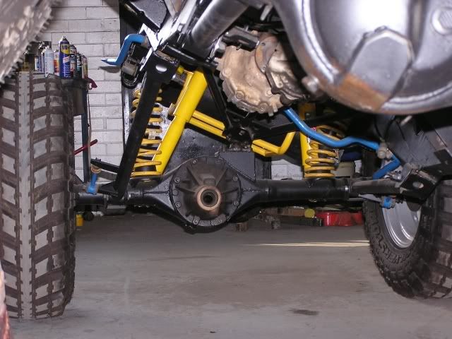
front with a-frame
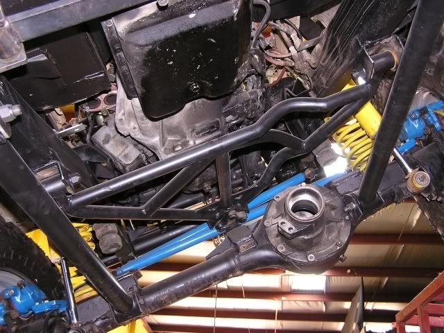
notice the angle of the rear arms, it will decrease when the vehicle is finished.
rear with parralel lowers
front with a-frame
notice the angle of the rear arms, it will decrease when the vehicle is finished.
lwb 1.6efi,4sp auto,f&r airlockers,dual t/cases.custom coils.builder of ROAD LEGAL custom suzukis...and other stuff.
CAD modelling-TECH drawings-DXF preparation.
http://www.auszookers.com/index.php
CAD modelling-TECH drawings-DXF preparation.
http://www.auszookers.com/index.php
This is a double tri angulated 4 link not an A frame so works alittle different.joeblow wrote:on the ones i have done i've made the distance from bushes to diff about 25% more than the distance between the bushes, and the lower control arms a minimum of 1/3 longer than the top length. then there is also the option of fully triangulated top and bottom.
angle of A frame = when looking down in plan view, there is an angle between the 2 arms that form the A. if this angle is less than a safe min(which im now reading as 40 degrees) it will not do the job of locating the axle lateraly. if the chassis mounts are as wide as they can be and the axle end is fixed, the lenght will change the angle. the longer the A frame the shallower the angle becomes.
I was refering to the actual shape of the A frame, not the straight line angle generated when extending a line from the pivot to bushes. Hence sugesting a string line mock up.
Obviously the longer the A frame with the same distance between the bushes at the chassis end will give more leverage against the bushes under lateral load. But increasing the A frame length, within reason, the difference between 40 degree and 45 degree would be neglegable.
Here is an example of an A frame that is not straight.
http://wizardperformance.com.au/index.p ... &Itemid=26
nastytroll wrote:This is a double tri angulated 4 link not an A frame so works alittle different.joeblow wrote:on the ones i have done i've made the distance from bushes to diff about 25% more than the distance between the bushes, and the lower control arms a minimum of 1/3 longer than the top length. then there is also the option of fully triangulated top and bottom.
angle of A frame = when looking down in plan view, there is an angle between the 2 arms that form the A. if this angle is less than a safe min(which im now reading as 40 degrees) it will not do the job of locating the axle lateraly. if the chassis mounts are as wide as they can be and the axle end is fixed, the lenght will change the angle. the longer the A frame the shallower the angle becomes.
I was refering to the actual shape of the A frame, not the straight line angle generated when extending a line from the pivot to bushes. Hence sugesting a string line mock up.
Obviously the longer the A frame with the same distance between the bushes at the chassis end will give more leverage against the bushes under lateral load. But increasing the A frame length, within reason, the difference between 40 degree and 45 degree would be neglegable.
Here is an example of an A frame that is not straight.
http://wizardperformance.com.au/index.p ... &Itemid=26
i understand that there is a difference between point to point and what shape it will be when fabricated.
im concerned about the asfety of the design. im guessing the safe min of 40 degrees would be referring to the point to point angle, not the fabed angle.
also you bring up a good point, an A frame is not a double triangulated 4 link, so i wonder if the Angle of the A frame becomes even more important for lateral stability than the uppers in a 4 link?????
i would like to triangulate the lowers, but if the rig has hyd rear steer the axle end can only be so wide, and the design of the chassis would not alow them to come under towards the center.
this rig would be a road driven tourer. flex is important but not the most important thing.
i know Strange Rover has made comments on how the effects of bolting portals onto a stock rover would effect the rear suspension working. thats where im coming from, to make the rear work better with portals and such...
serg
Who is online
Users browsing this forum: No registered users and 1 guest