The AC guy suggested that I could have got a complete new system installed for $1600 - yeah right! Or I could have got the parts from a wrecker and tried again for a re-gas....
OR
convert the broken AC system to an on board (or endless) air system.
Since the Lux isn't my only car I decided that rather than risk more money on an AC system I'd rarely use anyway I could try to turn it into an on board air compressor.
The internet search began.
I didn't find any guides on here (many threads with general questions) so when I finished the install I decided to write up my experience for all.
My Lux had a Sanden SD7H15 compressor so this guide applies to it but the Sanden SD5xxx is virtually the same with 5 instead of 7 pistons.
These were the best install guides I found on the net which gave me the info I needed to carry out the install:
The grungle one was the best all round, but mainly seemed to focus on mounting the compressor in a Patrol. I think I managed to cut the costs by quite a bit.
http://www.grungle.com/endlessair.html
http://www.visi.com/~bsimon/jeep/my_air.html
http://www.jeepforum.com/forum/f37/sand ... air-58213/
http://www.aulro.com/afvb/projects-tuto ... d-air.html
http://www.jpmagazine.com/techarticles/ ... to_01.html
This is the Sanden manual for the SD7H15 compresor
http://www.sanden.com/originals/images/ ... _Rev.2.pdf
The cheapest way I found to complete the install was to buy a small 8L compressor form Supercheap.
At the time the Black Ridge BRI40 compressor was $79 - normally $99. It is a cheap compressor from China but it provides most of the main components required (other than the AC compressor that I already had).
- 8L air tank
- manifold
- pressure switch
- non-return valve
- safety valve
- pressure guage
Other parts needed were various thread adaptors and tail fittings - I had many of those already.
This is the link to the one I bought
http://www.supercheapauto.com.au/online ... 0101#Cross
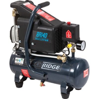
The Compressor
Step one in the install is to decide how the compressor will be lubricated. Normally it is lubricated by the oil in the refrigerant but when used for Air that isn't an option anymore.
The two options I found in my searches were using an in-line oiler and a corresponding oil trap after the compressor or converting the compressor to use internal grease.
I opted for the grease option as it required less parts I didn't already have and seemed more maintenance free (at least less frequent).
For Sanden compressors the mod required for running grease in the compressor is blocking up a hole that normally allows the refrigerant oil to pass into the workings of the compressor.
After the rear of the compressor is removed the hole shown below needs to be blocked. Grungle chose to block the hole in the 5mm thick plate but to me it seemed easier to block the hole into the compressor housing its self.
This is how it looks when the rear is removed.
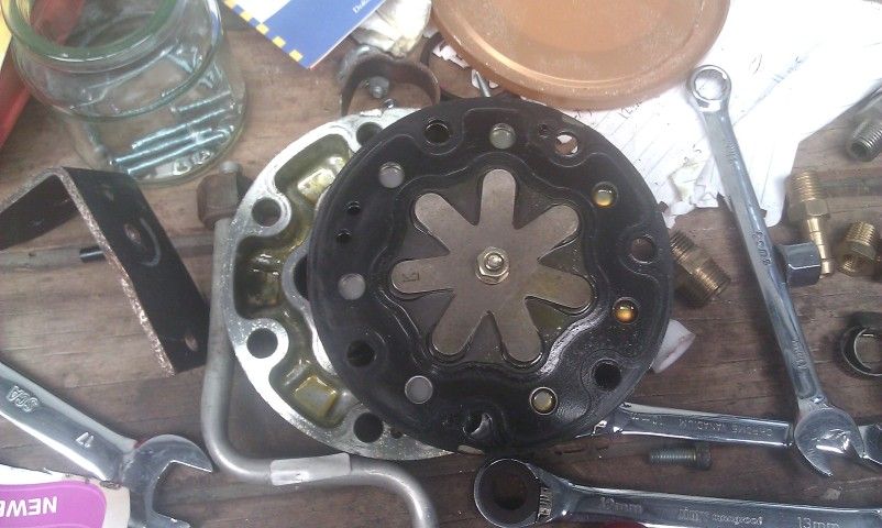
View without the rear housing and the oil passage blocked
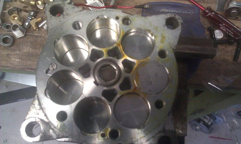
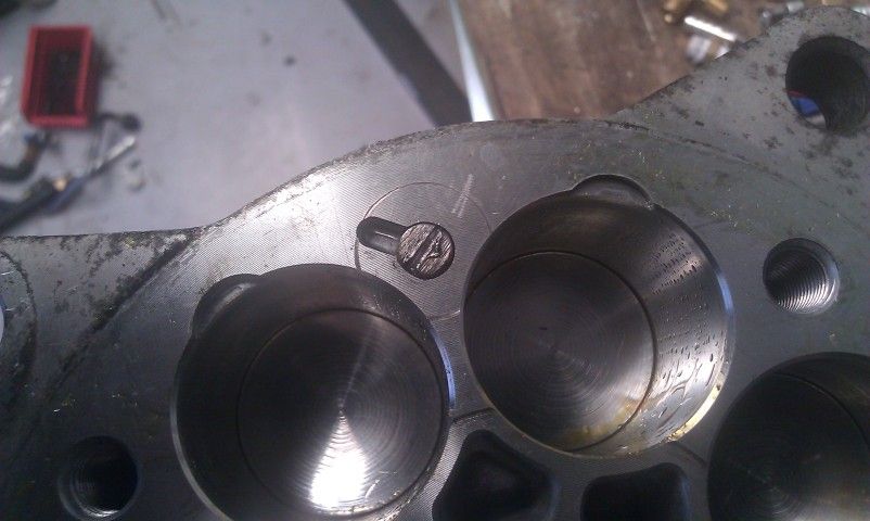
I just used a bolt of appropriate size to tap the hole then removed it and cut the head off and put a slot in it for future removal if required.
Once the passage is blocked and the compressor is back together you put grease in through the port on the top. It's possible to fit a grease nipple or simply pump the grease in through the hole when the bolt is removed. I didn't get a pic of that but there are pics in the Grungle thread.
Connections to and from the AC compressor
Since I had a complete AC system to use I simply put a filter on the end of the low pressure hose to stop debris entering the compressor.
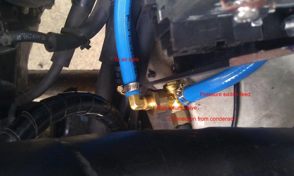
I connected the inlet for the air tank to the outlet on the AC condensor (small radiator-like element in front of the radiator). The reason I retained the condensor was because it was easier to leave it in and would also cool the air form the compressor allowing me to use normal (ie not high temp) air line.
The image below shows where the connections went. I removed the non return from the tank so it would be close to the pressure switch in the engine bay.
Modifying the tank
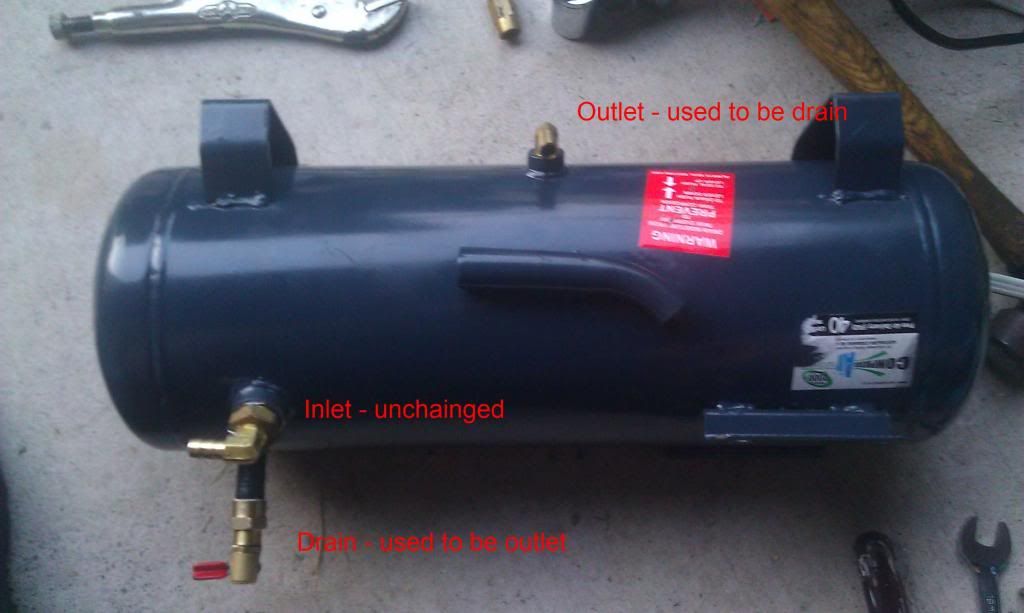
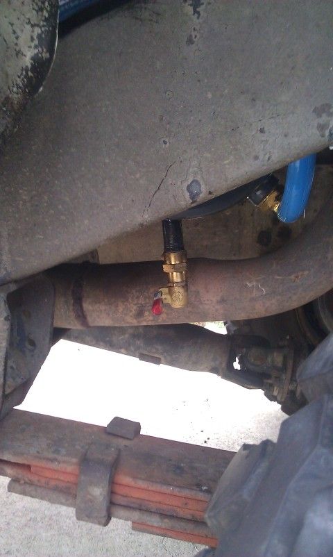
For ease of mounting I decided to swap the outlet and drain fittings.
To do this brass fittings are required. I don't know the exact details of these as I had some spares. The rest of the fittings and air hose that I had to buy I got from Masters as they had a huge range of fittings. Most were $8 or less.
The tank after mods
Hose connections
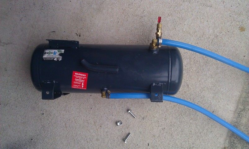
The tail fittings and adaptors are all fitted to the tank as below. The only leaks I had when I was finished were from the tail fittings which simply required the hose clamps to be tightened.
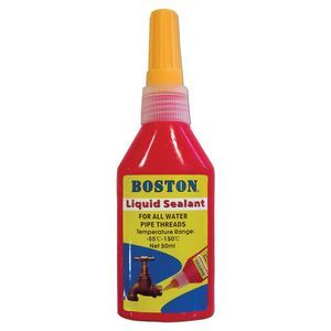
I used this thread sealant which cost $4.90 in the plumbing section at Masters rather than teflon tape. Even though it says for water sealing on the front it is also rated to seal gas on the back.
Mounting the tank
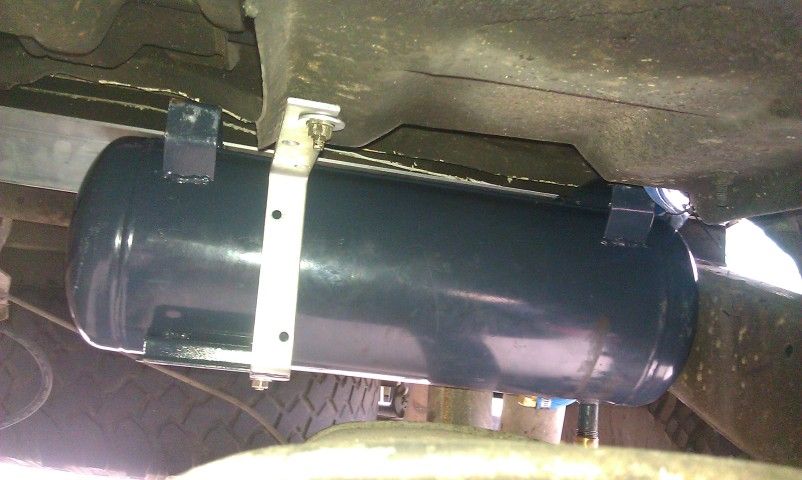
I found a good spot under the tray of the Hilux and used some 50x50 aluminium angle and a zinc angle bracket to hang the tank.
Steel would have been better and might not have required the zinc bracket but I had the aluminum so used it. The bracket stops any movement so the aluminum shouldn't flex and weaken.
The aluminium runs between the two front tray mount bolts.
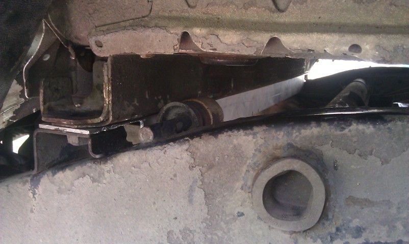
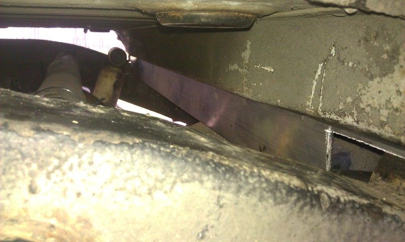
The tank was then bolted to the angle - the pic was test fitting, I didn't try to put the angle in with the tank attached.
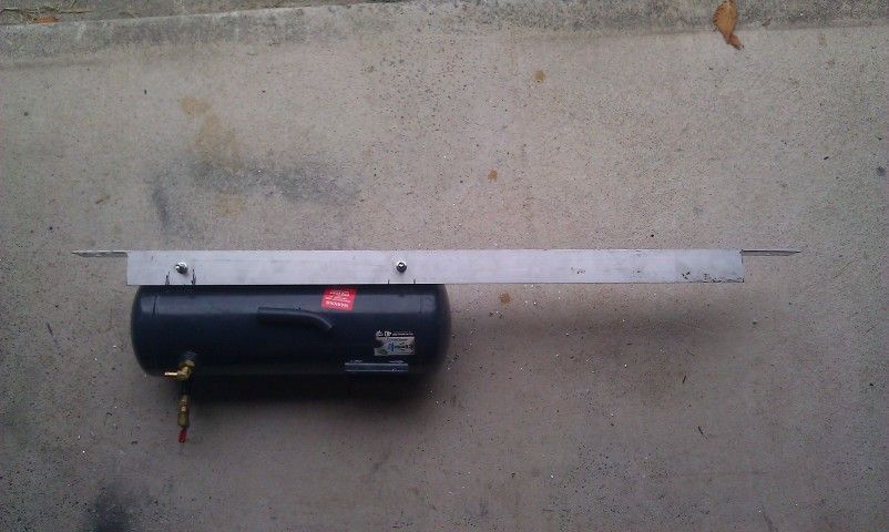
And here is the tank with the bracket attached
The tank drain is easily accessible - exhaust looks closer than it is.
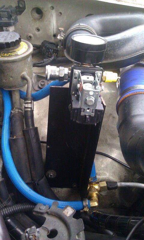
The manifold and pressure switch
After removing the switch and non return from the tank I mounted them on a piece of angle in the engine bay. There were already some tapped holes that could be used.
The lower hose is the inlet to the air tank. The hose connecting the non return to the pressure switch (obscured by the bracket) provides the input to activate the pressure switch when 120psi is reached.
The top hose is from the outlet of the tank to the manifold that feeds the nitto outlet connector.
Electrical connection
The clutch on the compressor is activated by a 12v feed. The pressure switch is used to control this so the compressor only comes on when required.
I ran a connection from the switched, fused power on my UHF to one side of the pressure switch then on to the compressor clutch.
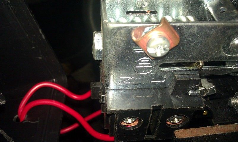
Pulling the red toggle switch on top of the pressure switch up activates the compressor until 120psi is reached. When the pressure drops below 80psi it turns the compressor back on.
How does it perform
I did a few simple tests that I used my phone to record.
First was how long it took to fill the system at engine idle. In the vid it starts filling when I pull the toggle and there is an audible hiss at around 7 sec. It fills to 120 psi when the pressure switch kicks in after around 1:35
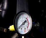
The next test was inflating my 32" tyre from around 32psi up to 40psi. It took close enough to 30 seconds with me stopping to check pressure a couple of times. That was using a $12 inflator I picked up at Masters - not sure if better ones flow faster.

The final test was inflating an old 31" tyre with a slow puncture from dead flat up to 30psi. I start inflating at around the 17sec mark in the video and it gets to 30psi after close enough to 1:30. After the tyre is inflated the system is still at a little under 60psi.
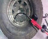
I left the system at 90psi overnight and in 12hrs lost under 5psi so it is fairly well sealed.
All up I'd say I spent around $120 on it but even if I had to buy most of the parts I'd say it could easily be done for under $200 assuming the AC compressor is already on the car.