Notice: We request that you don't just set up a new account at this time if you are a previous user.
If you used to be one of our moderators, please feel free to reach out to Chris via the facebook Outerlimits4x4 group and he will get you set back up with access should he need you.
If you used to be one of our moderators, please feel free to reach out to Chris via the facebook Outerlimits4x4 group and he will get you set back up with access should he need you.
Recovery:If you cannot access your old email address and don't remember your password, please click here to log a change of email address so you can do a password reset.
strengthening diff housings
Moderator: Micka
strengthening diff housings
Did a search but couldn't find anything, anyway was about to spray my diff housings for my toy conversion, when i thought i may aswell make the housings a bit stronger but was after some photo's or info on what other guys have done.
Damien
Damien
diff housing
I have a maxi-drive laminated housing, when i pulled it apart to get LRA to mod the swivel housings (castor correction) i noticed that the axle tubes had steel pipe welded inside the original tubes and the outside is heavily braced.
I'll get a couple of shot of the exterior for you. soon
I'll get a couple of shot of the exterior for you. soon
86 Rangie, F+R 4:11 Maxi, 35 Pedes, 6 point cage, Comp High Mount
Re: diff housing
When I last spoke to Mal (Maxi_Drive) about this, he said he no longer tubed the inside, as it adds a lot of extra weight bit not much strength. He now only welds the bracing outside.schuler wrote:I have a maxi-drive laminated housing, when i pulled it apart to get LRA to mod the swivel housings (castor correction) i noticed that the axle tubes had steel pipe welded inside the original tubes and the outside is heavily braced.
I'll get a couple of shot of the exterior for you. soon
oildripa - yours looks strong but you lose a lot of clearance. Bracing on top is better IMO.
_____________________________________________________________
RUFF wrote:Beally STFU Your becoming a real PITA.
Bracing below the axle will be far superior to above.
Steel operates best in tension not compression.
The diff centre is the real limiting factor on any diff. The laminating is above the level of the bottom of the diff centre at all times.
I have Maxi laminated diffs front and rear and in 11 years haven't had a problem.
Steel operates best in tension not compression.
The diff centre is the real limiting factor on any diff. The laminating is above the level of the bottom of the diff centre at all times.
I have Maxi laminated diffs front and rear and in 11 years haven't had a problem.
Cheers,
Zuffen
There's no such a thing as too much horsepower
Zuffen
There's no such a thing as too much horsepower
Pics of MD diff housing
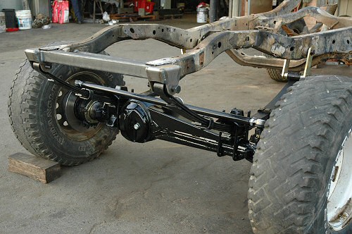
Here are the pics of mine as you can see the laminating does not impede on ground clearance.
The housing was heavier but not that much, when you think about it what difference will 3 foot of tube weigh.
Steve
The housing was heavier but not that much, when you think about it what difference will 3 foot of tube weigh.
Steve
You do not have the required permissions to view the files attached to this post.
86 Rangie, F+R 4:11 Maxi, 35 Pedes, 6 point cage, Comp High Mount
I agree, but in my experience every bit of clearance counts. Plenty of times I have managed to find room between the rocks to squeeze the diffs through, but have had rocks contact the diff tubes.zuffen wrote:Bracing below the axle will be far superior to above.
Steel operates best in tension not compression.
The Maxi-Drive method schuler posted doesn't effect the clearance to a great extent.
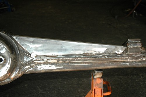
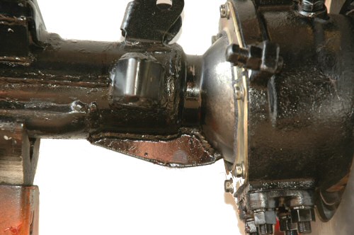
Although not as strong, I think bracing on top of the axle has its merits (this is a brace on the top of a competition toyota axle):

It is combined with some subtle lower bracing though:


_____________________________________________________________
RUFF wrote:Beally STFU Your becoming a real PITA.
There is nothing wrong with steel in compession, strength is the same provided it does not buckle.
The kind of bracing, which forms a box section will not buckle (it could if extremely thin, but no one would use material that thin).
A diff housing is mainly loaded as a beam. One side of a beam is in compression and the other side is in tension (unless it is pre-tensioned, as in concrete bridge spans).
I would put the bracing on top, rather than reducing ground clearance.
John
I think you two are both correct, all that matters as if you have the brace in compression then it needs to be made of an adequate material thickness and section, and in tension likewise. I do prefer the more ground clearance approach though.
This is something I will have to look at, with the weight of my motor over the front wheels, not that I push it hard, but all it takes is innattention and 1 washout....
Just remember at all times try to keep unsprung weight to a minimum, using large section thin wall material where possible.
JC
This is something I will have to look at, with the weight of my motor over the front wheels, not that I push it hard, but all it takes is innattention and 1 washout....
Just remember at all times try to keep unsprung weight to a minimum, using large section thin wall material where possible.
JC
'92 Rangie Sherwood/turbo intercooled isuzu4BD1 /ACE/ full leather/2.5" exh/2.5" body lift/DeCarbon shocks/LR tanks/LT95 back in and OK now, Sals conversion soon...
As I stated above, a diff housing is loaded as a beam. An important factor governing the material stress in a beam is the bending moment.
For a diff housing there are vertical loads acting at the wheels and the springs. Assuming no other vertical loads (ie not sitting on a rock between the spring locations), this loading arrangement results in a bending moment distribution that is zero at the wheels and increases to a maximum at the spring locations. The bending moment is linear between the spring locations.
If the diff housing is sitting on a rock, between the spring locations, or the mound between wheel ruts, and the wheels are still carrying a good proportion of the weight, the bending moment will reduce, between the spring locations.
If most of the weight is on the rock and little or no weight is carried by the wheels, the bending moment will reverse sign and become a maximum at the location of the rock. In this case the bottom of the housing is in compression and the upper part is in tension.
If the main purpose of the strengthening is to resist the loading from a heavier engine and hitting bumps harder with the wheels (not hitting rocks hard with the diff housing). It is more important that the strengthen of the housing extends under the springs where the bending moment is greatest. In this case it is not necessary for the depth of the bracing to increase at the diff pumpkin as shown in some of the pics.
The cases are similar for horizontal loads except there is no horizontal load at coil spring locations, just at the wheels and front radius arms (or rear trailing arms and rear A-frame). Again there can be an impact with an object between the radius arms.
Also it is import to not have sudden changes of section, as this causes severe stress concentrations, leading to possible fatigue failure.
Welds across the tension side of a beam are also bad for fatigue strength.
John
Who is online
Users browsing this forum: No registered users and 2 guests
