Notice: We request that you don't just set up a new account at this time if you are a previous user.
If you used to be one of our moderators, please feel free to reach out to Chris via the facebook Outerlimits4x4 group and he will get you set back up with access should he need you.
Recovery:If you cannot access your old email address and don't remember your password, please click here to log a change of email address so you can do a password reset.
Jimny Supercharged
Jimny Supercharged
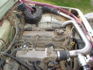
Hi guys, a little tech thread about fitting an AMR300 supercharger to a G13BB
Details:
It runs 5psi with standard pulleys
AMR300 has 50mm inlet and 43 mm outlet pipes.
I have tapped into my o2 sensor to monitor air/fuel ratios everything seems to be fine atm.
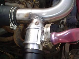
I tig'd in a cheap BOV to relief the pressure from the intake track when the throttle is shut.
I have to run a plumb back system as when im cruising in any gear with the throttle closed there is too much air in the intake track and when the BOV releases to atmosphere its far to loud and continues to release because of the supercharger constantly boosting as its connected to the engine.
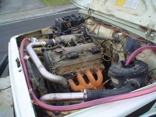
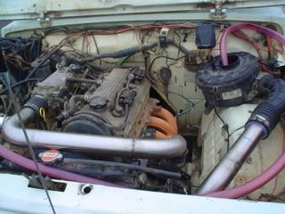
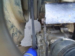
The supercharger is connected via a 4 rib belt via the standard double crank pulley on the g13bb and goes around the powersteering pump as well.
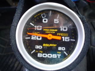
Performance wise its really good, heaps more low down power and has 5psi of boost from idle, so as soon as i open the throttle 5psi is there.
Just posting this to answer any questions as i know this topic has come up alot.
pics
the plumb back system was just in the testing phase at this point, hence the tubing used.
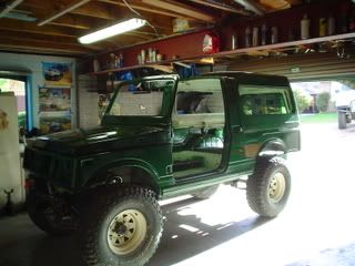
and its going in this
Last edited by Spike_Sierra on Thu Jan 08, 2009 3:15 pm, edited 1 time in total.
85 LWB w. FRP Canopy
Ca18det conversion in progress, Vit PS, RUF,
6.5:1's, 33x12.5 Bfg's, custom front and rear bars.
Ca18det conversion in progress, Vit PS, RUF,
6.5:1's, 33x12.5 Bfg's, custom front and rear bars.
if mud4b is looking at this, did you run a bov with your set up?, if not where did you excess air go when the throttle was shut
also, you said you ran 9psi on yours, just wondering how this was achieved as i have standard pulleys and it boosts around 5psi.
more pics
at idle, throttle shut
also, you said you ran 9psi on yours, just wondering how this was achieved as i have standard pulleys and it boosts around 5psi.
more pics
at idle, throttle shut
85 LWB w. FRP Canopy
Ca18det conversion in progress, Vit PS, RUF,
6.5:1's, 33x12.5 Bfg's, custom front and rear bars.
Ca18det conversion in progress, Vit PS, RUF,
6.5:1's, 33x12.5 Bfg's, custom front and rear bars.
just an update, noone seems to have anything else to add, so...
just took it for a test drive, little throttle is needed in any gear to get it up and going, it just cruises off about 1/5th throttle. Took it for a test along a gravel road, not much is needed to get it offtrack and crossed up especially with the locker in.
Most of the noise is from the sound of the air coming out of the BOV(as you can here the internals of the charger in this air), what i should have done was tig the BOV over the other side(just above outlet to supercharger) as this would have made it easier to plumb straight into intake side of s/c. I will just have to run a longer plumb back tube and tig a joiner pipe into the intake side. It has the same feeling as putting in new gearing, as i can now cruise in an even higher gear than before and still be pulling away.
Feel free to ask any questions.
85 LWB w. FRP Canopy
Ca18det conversion in progress, Vit PS, RUF,
6.5:1's, 33x12.5 Bfg's, custom front and rear bars.
Ca18det conversion in progress, Vit PS, RUF,
6.5:1's, 33x12.5 Bfg's, custom front and rear bars.
Good tech spike. To achieve a higher PSI from the s/c would you run a smaller diameter pulley on the s/c?
Work - KPD4X4.COM - KPD Industries Australian Distributor of Diesel Power Modules - Germany.
Play - dank's zook
Play - dank's zook
correct dank, just like bikes gearing, to spin the back wheel faster you either have to change the rear cog to a smaller on(the supercharger pulley) or change the front cog to a bigger one (the crankshaft pulley), I just wanted to find out from Mark why his and Beallys sc was running 10psi when mine is only 5psi. when pulleys wouldnt be that different in size, if any at all. As you can see in the pics, the pulley on the sc is quite small as it is, and there is to much work to try and change either pulley, im very happy with the pressure running atm.
85 LWB w. FRP Canopy
Ca18det conversion in progress, Vit PS, RUF,
6.5:1's, 33x12.5 Bfg's, custom front and rear bars.
Ca18det conversion in progress, Vit PS, RUF,
6.5:1's, 33x12.5 Bfg's, custom front and rear bars.
Spike,
What are the stats on the AMR300?
I don't know much about super chargers - so here come the silly q's:
1. what vehicle have you sourced it from
2. what are the dimensions of the charger
3. do you have any shots of the charger outside of the vehicle (i.e. showing location of inlet and outlets)
Do you have any 'seat of the pants' power ratings to tell us if it was a worth while swap?
Thanks,
Greg
DMA Founding Member #1 - Now Retired
good questions Greg,greg wrote:Spike,
What are the stats on the AMR300?
I don't know much about super chargers - so here come the silly q's:
1. what vehicle have you sourced it from
2. what are the dimensions of the charger
3. do you have any shots of the charger outside of the vehicle (i.e. showing location of inlet and outlets)
Do you have any 'seat of the pants' power ratings to tell us if it was a worth while swap?
Thanks,
Greg
I sourced mine from EBay for around $275, theres a bloke that regularly sells them on here, im guessing he runs an import shop.
straight from autometer topic - Supercharger Steal Pt 1
Subaru EN07
This supercharger is, in a word, tiny.
The pipe which has the tubes coming off it is the inlet, and the un-piped one, the outlet.
Fitted to upmarket versions of the Japanese-market Subaru Vivio/Pleo, this blower is lightweight and can be squeezed in very tight engine bays. It measures approximately 18.5cm in length (including the pulley) and the main body is around 15cm wide and 10.5cm tall. Although fitted by Subaru, the blower is manufactured by Aisin and is coded AMR300. This code suggests it displaces 300cc of induction air per revolution.
The 660cc supercharged Vivio engine is rated at the class regulation 47kW and has 84Nm of torque, so the AMR300 blower is suitable for only low power applications. This makes sense when you look at the small 45mm OD blower outlet pipe.
We’d be reluctant to push the AMR300 supercharger past 70kW - which means it’s good for only sub 1.0-litre engines.
Seat of the pants, im no good with estimates but there is definately an increase, and not the same increase you feel when you have a 2in exhaust fitted...ie...nothing bar noise...
The jimny engine, even though it has no VVTI or Vtec it feels as if it gets an extra kick at around 4000-4500 rpm, and now with the charger on, this kick you can definately feel.
When i first connected it up, i didnt have the BOV fitted so i was out testing and one of the pipes to the intake manifold blew off from too much excess pressure in the intake track, when this blew off, the instantaneous change in power was evident. Thats my seat of the pants guess. I havnt been out testing to a great extent yet, but when i have the BOV fitted properly, i will head out along the roads that usually give the engine a run for its mula and will see if there is a change in speed.
So in conclusion, i feel that for around $300(the price of an average exh system or webber carb) that it was a worthwhile swap. I sourced the piping for free and already had some rubber tubing at home. I have a mate with a tig, so i tig'd the piping up myself to save money. Big thanks to Danny, Jarrod and Phil for there help too.
Regarding the question before about noise, i will try and get a video of it to show how quiet it is with the piping connected, but without piping it was similar to this Amr300 in a Mira
85 LWB w. FRP Canopy
Ca18det conversion in progress, Vit PS, RUF,
6.5:1's, 33x12.5 Bfg's, custom front and rear bars.
Ca18det conversion in progress, Vit PS, RUF,
6.5:1's, 33x12.5 Bfg's, custom front and rear bars.
I guess you could unplug the air ducting and do a 0-100km/h test, then repeat with the ducting attached? that would give an approx idea if your pants aren't very accurateSpike_Sierra wrote: Seat of the pants, im no good with estimates but there is definately an increase, and not the same increase you feel when you have a 2in exhaust fitted...ie...nothing bar noise...
DMA Founding Member #1 - Now Retired
Spike, since you have the motor and supercharger in front of you - do you think there is any chance it would like up to fit under on the other side of the motor next to the alternator? i ask because the passenger side is already quite busy on my engine, and it would dramatically reduce the inlet piping since i have the air box at the front on the drivers side.
Do we know how much boost these engines will take happily?
DMA Founding Member #1 - Now Retired
nicbeer wrote:have u done any other fueling mods? or ecu tricks?
as i am having some thoughts
I haven't as yet Nic as the air/fuel meter has kept within limits, however i have made up an adjustable map sensor which is stole from gojeeps adjustable Map sensor modification
This will modify the signal sent to the ecu from the map sensors variable 5v signal to hopefully modify injector pulse, which i can check through the o2 sensor.
greg wrote:Spike, since you have the motor and supercharger in front of you - do you think there is any chance it would like up to fit under on the other side of the motor next to the alternator? i ask because the passenger side is already quite busy on my engine, and it would dramatically reduce the inlet piping since i have the air box at the front on the drivers side.
Do we know how much boost these engines will take happily?
From reading around around the 7-8psi range, which is common on many N/A cars, however I can not conclude that this is factual information.
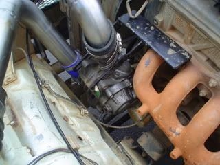
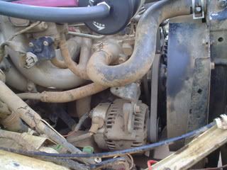
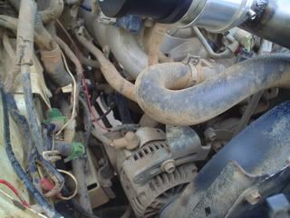
Regarding fitting on the alt side of engine, I took some photos. What engine do you run Greg?
Main problems on fitting it this side is top radiator hose, alternator(even worse if a ford unit was being used), in my case the steering linkage with the angle of the Vit box and water pipes that are all in this area. I can still fit a Vit P/S pump ontop of the angle bracket that the S/C is mounted on, and it runs just under the bent inlet tubes. What else do you have on that side? A/C?
Regarding the 0-100 test, should be able to manage that, need to find a road suitable, but I'm onto it.
pics.
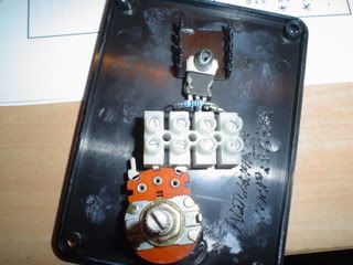
Adj map sensor nearly finished. The dial is used to alter the original 5v signal and theres also a switch to be added to switch between old and new voltages.
85 LWB w. FRP Canopy
Ca18det conversion in progress, Vit PS, RUF,
6.5:1's, 33x12.5 Bfg's, custom front and rear bars.
Ca18det conversion in progress, Vit PS, RUF,
6.5:1's, 33x12.5 Bfg's, custom front and rear bars.
Sorry Spike - i had a look at my engine bay last night - there is clearly no way it would fit on the drivers side.Spike_Sierra wrote:Regarding fitting on the alt side of engine, I took some photos. What engine do you run Greg?
Main problems on fitting it this side is top radiator hose, alternator(even worse if a ford unit was being used), in my case the steering linkage with the angle of the Vit box and water pipes that are all in this area. I can still fit a Vit P/S pump ontop of the angle bracket that the S/C is mounted on, and it runs just under the bent inlet tubes. What else do you have on that side? A/C?
My engine is the G13BB with an endless air (bottom) and AU Falcon power steer pump (top) on the passenger side.
Maybe i will just have to get one of those 12V superchargers instead
DMA Founding Member #1 - Now Retired
ah good choice of enginegreg wrote:Sorry Spike - i had a look at my engine bay last night - there is clearly no way it would fit on the drivers side.Spike_Sierra wrote:Regarding fitting on the alt side of engine, I took some photos. What engine do you run Greg?
Main problems on fitting it this side is top radiator hose, alternator(even worse if a ford unit was being used), in my case the steering linkage with the angle of the Vit box and water pipes that are all in this area. I can still fit a Vit P/S pump ontop of the angle bracket that the S/C is mounted on, and it runs just under the bent inlet tubes. What else do you have on that side? A/C?
My engine is the G13BB with an endless air (bottom) and AU Falcon power steer pump (top) on the passenger side.
Maybe i will just have to get one of those 12V superchargers instead
yeah those 12v superchargers work a treat, or so everyones feedback message says.
85 LWB w. FRP Canopy
Ca18det conversion in progress, Vit PS, RUF,
6.5:1's, 33x12.5 Bfg's, custom front and rear bars.
Ca18det conversion in progress, Vit PS, RUF,
6.5:1's, 33x12.5 Bfg's, custom front and rear bars.
update,
went for a longer run tonight, and noticed it does lean out, as it was still warming up the last times hence was running richer then normal. I went for a run up the highway and noticed pinging, which i think can be put down to the lean fuel mixture and heat of the inlet temps.
now i have two options that i can see
1.put a resistor in the engine coolant temp sensor line to trick the ECU into thinking its cold aka bathurst skyline style
2.Rig up the adjustable MAP sensor from gojeeps website. I have built it but broke a fin off the regulator so need to get another before i can test this. This map sensor will regulate the 5v going into the map sensor putting more voltage in which will give more voltage out, and keep the injectors open for longer.
Any other ways that i can tune the air/fuel ratio without spending big dollars on new computers as I want to see if it is possible to boost a jimny engine on the cheap.
85 LWB w. FRP Canopy
Ca18det conversion in progress, Vit PS, RUF,
6.5:1's, 33x12.5 Bfg's, custom front and rear bars.
Ca18det conversion in progress, Vit PS, RUF,
6.5:1's, 33x12.5 Bfg's, custom front and rear bars.
This would work or just an adjustable fuel reg. Now im not sure about the MAP sensor voltage idea. The MAP sensor in the jimmy or in most N/A cars are a 1bar or 14.7psi. This is atmospheric pressure and thus the MAP sensor will only read vacuum and possibly very very slight boost. Most MAP sensors output 5V or very close to it (4.7) at atmospheric pressure ie WOT when there is very low vacuum in the intake manifold. When the throttle is shut, high vac is produce and the MAP outputs around 0-1V. So in effect adding this voltage will only effect the engine running less than WOT with no boost ie vacuum in the manifold.BenT wrote:How about a rising rate fuel pressure regulator?
Ben
I would have a play with the air intake temperature sensor and the coolant temperature sensor, although you have to check weather they are negative temperature coefficient (NTC) or positive temperature coefficient (PTC) sensor types. They either increase or decrease in resistance and thus voltage due to temperature. Once you work this out then you either add a parallel resistor to them, to drop the sensor overall resistance) or series resistance to increase overall resistance. Once again this all depends on the type of sensors used and their internal resistance.
Hope it makes sense
Dan
hey spike, because mark has not responded , i thought i would let you know in a different thread he said his didn't run real well till he put a turbo surf map sensor on it. i can't imagine they would cost too much from a wrecker to try...... but let us know how you get on, i'm keen to see what happens.
WANTED: swb vitara rear seat. the 3 seater bench type
for sale: wt diffs, snake hi steer, maruti 4.1 wt centres,
Jr Zook, i got the idea of gojeep website and also autospeed,
Heres what they say
----------------------------------------
So that you can electrically fool the ECU into giving the right mixtures, you need to examine the pin-outs of the airflow meter or MAP sensor. A power feed to the sensor (usually 5 volts), an earth, and a signal wire should be able to be located. In vane-type airflow meters, an air temp sensor is also used, but you can ignore that. Whether the sensor's output voltage rises or falls with increasing engine load doesn't matter when using this circuit. However, this approach cannot be used with airflow meters or MAP sensors that have a variable frequency output.
Two potentiometers (abbreviated to 'pots') are used. Both are 10 kilo-ohm linear designs; they cost about A$2 each from an electronics store. A pot works as a variable voltage divider, allowing the central wiper contact to be skewed to one voltage or another. In the circuit used here, one of the pots is connected between the 5 volt supply wire and earth. With this pot's wiper at the 5 volt end, that's the voltage available on the wiper terminal. With the wiper at the earth end, there will be no voltage available. Pot 2 connects between the wiper of Pot 1 and the signal output wire of the sensor. Moving the wiper arm of this pot (which goes to the ECU) will cause the signal to be either closer in level to the sensor output, or to the voltage provided by Pot 1.
The wiring is simple, and the use of the pots even simpler. To start the car, set both pots to their central positions. Disconnect the oxygen sensor from the ECU, so that it can't go into closed loop mode - this causes constant cycling of the mixtures. Use Pot 1 as a coarse mixture control, and Pot 2 as fine adjustment.
Start off by setting light loads. When the light load adjustment is about right, lift the power level required and re-do the fine-tuning using Pot 2. Obviously it's more important to get the high loads right than the light loads, but when the mixtures are set perfectly for high load conditions then they may not be right at light loads because of non-linearity in the engine's fuel needs when compared with its unmodified state. If the light loads look a bit too rich, don't worry - when the o2 sensor is plugged back in the ecu will relearn.
-----------------------------------------------
Mr Green - I will see if i can track down a cheap map sensor from a TD surf. Thanks for that.
---------
JrZook and BenT
few question regarding this fuel pressure reg,
Where do I get one from?
Where does it go?
How can it be adjusted?
Extra info, I run a standard Vl pump.
Thanks All
edit: After more procratination from studying i found this,
info on fuel pressure regs and supercharger set ups
85 LWB w. FRP Canopy
Ca18det conversion in progress, Vit PS, RUF,
6.5:1's, 33x12.5 Bfg's, custom front and rear bars.
Ca18det conversion in progress, Vit PS, RUF,
6.5:1's, 33x12.5 Bfg's, custom front and rear bars.
Ebay: Ebay rising rate regulatorSpike_Sierra wrote: JrZook and BenT
few question regarding this fuel pressure reg,
Where do I get one from?
Where does it go?
How can it be adjusted?
Doesn't specifically say it is rising rate, but if you look carefully, it has an input, output, and a boost reference port. I've seen the same one advertised elsewhere as rising rate.
It goes in the return line, and produces back pressure on the factory regulator when the boost comes on, which increases the pressure at the injectors.
It has a screw in the top for base adjustment, but I'm not sure if that also affects the rising rate. You will see rising rate regulators sold as different ratios, e.g 1:1, 2:1, 3:1 etc. i.e the fuel pressure increases the same as the boost, twice as much, three times as much etc.
Ben
WWW.ZUKPARTS.COM - Quality Suzuki Off-road Parts - 1600 Adaptor kits - Vitara Power Steering adaptor kits - Disc brake kits - Heavy Duty Transfer case arms & more
I'll just concentrate on the 70kw part I wonder how they work out their figures....ofr57 wrote:but your running it in a 1.3 nice blower thoughWe’d be reluctant to push the AMR300 supercharger past 70kW - which means it’s good for only sub 1.0-litre engines
BenT - good idea, thanks for checking that out for me. I guess that seems like a reasonable idea and pretty cheap and simple. Pity the return lines are in such a PITA location, maybe i could extend it so it loops up near the firewall.
JrZook, regarding the coolant temp sensor, is there a way to check with a normal multimeter if the resistant is increased or decreased with temperature. You seem like you know your stuff, thanks for your help.
85 LWB w. FRP Canopy
Ca18det conversion in progress, Vit PS, RUF,
6.5:1's, 33x12.5 Bfg's, custom front and rear bars.
Ca18det conversion in progress, Vit PS, RUF,
6.5:1's, 33x12.5 Bfg's, custom front and rear bars.
In regards to the temp sensors, yes there is an easy way to measure their output resistance. Since they are simple a thermistor, take the plug off them and measure the resistance between the two terminals of the sensor with a multimeter. Do two measurements, one when the engine is cold and one when the engine has reached operating temperature. Also do the same for the air intake temp sensor. Need to know their characteristics first before even attempting to play with them.
As for the MAP sensor. Do you have a pic of it? Is it mounted to the firewall and what brand? I will try and elaborate on the adjustable MAP sensor case to make it a tad more understandable.
Firstly MAP sensors output a voltage between 0-5V dependent on engine load.
The ecu requires an input signal of between 0-5V, over 5 smoke usually comes out
Let us consider an NA engine, with the appropriate std MAP sensor (14.7psi - atmospheric).
At WOT ie full engine load, depending on sensor type, the sensor output usually swings very close to full rail voltage (either 0 or 5 volts).
For an example we will assume that the MAP sensor is at roughly 5 volts at full load (WOT) and 0 at no load (deceleration or idle).
Now the timing map/fuel map in the ecu for full load will retard timing and increase fuel (injector pulse width) under these conditions to avoid pinging and provide enough fuel to stop leaning out for the load conditions.
If the MAP sensor is already outputting 5v, the ecu has already determined this as a full load condition, and provides the most fuel and timing retard that the factory timing/fuel map has been programmed with, ie there are no further enrichment or retard settings in the factory maps, it is maxed out!
Now with the added boost the MAP signal will hit 5v at alot lighter loads, since it is a atmospheric sensor, hence is maxed out once your boost guage hits 0, as at this point the intake has atmospheric pressure and for an NA engine its determined as full load condition. So this is the limit of the factory fuel and timing map, although now we have to deal with positive pressures above atmospheric, boost!
So this twin pot adjustment circuit claims to provide 'tuning' of the MAP sensor output voltage. In fact this is true, it will adjust the output of the MAP and hence will trick the ecu in thinking it is at a different load condition. Ok, so we what additional fuel and timing redardment upon boost. We use this circuit to start tuning at low loads, then we hit atmospheric manifold conditions and positive boost. Hurrmmmm the output voltage of the MAP is already at 5V, the only thing we can do with the circuit is drop voltages. Well this would be a step backwards because we would be tricking the ecu into thinking there is less load and hence reduce fuel and increase timing, fact is we are starting to get on boost, we need more fuel less timing. This is where the problem arises for this particular fix, we have already given the ecu the voltage corresponding to max fuel max retard for max load, there are no further enhancements out of the factory maps.
Second option, replace MAP sensor for a boost compatible type ie 2 bar. Goodo now this sensors provides us with 5V at 14.7psi boost(14.7 above atmospheric-max load) say 2.5V at atmospheric and zero again on idle or deacceleration (min load). Whats the problem here?? Well the factory fuel/timing maps are still the same. So now at atmospheric manifold pressure we have 2.5v instead of 5v at the ecu. Thus the ecu thinks we are at half load when infact originally we were at full load unboosted (NA). Problem again we have less fuel and too much timing advance for the actual engine load, we lean out quicker than before.
Now this is most likely the case from the Turbo surf MAP sensor, although i cant comment on how mud4b's machine performed better with it, abiding the facts above.
Again ecu's are much more complex than what i have stated above, this is a general overview concerning the ecu and MAP sensor. The temp sensors on the other hand alter the factory maps by introducing timing and fueling offests for warm up etc etc, and hence will provide different map offsets regardless of engine load/rpm etc. For instance a cold engine requires more fuel because the fuel doesn't atomize properly, the timing is also reduced because of this and to reduce the possibilities of detonation cause by a lean state due to the non fully atomized fuel mixture. Hence this tweak may help your cause under boost conditions.
I still believe for simplicity case try your luck with an adjustable or rising rate fuel reg. This will fuel the beast better under boost but will do nothing for altering the factory timing. Temp sensor mods may help this.
All the info i have provided is under my understandings of general EFI systems based on GM 1bar MAP sensors. This theory is currently in use to developing my own 'home brew' EFI system including microprocessor algorithms, sensors etc etc. Im not claiming to know all but can try to answer quires to the best of my knowledge.
Sorry for the lonnnnnnnnnnggg post, hope it helps your understand of what the MAP sensor does and how it affects the ecu.
Cheers Dan
I dont know about beast, unless you are referring to leaning out and detonation as the beast...JrZook wrote:cut....This will fuel the beast better under boost
thanks for that Dan, you definatly know your stuff.
I will have to do some reading on taking resistance measurements and suss out the coolant temp, however i dont currently have the air temp sensor connected as i cant keep it sealed in the intake track due to the boost, but im guessing it wont matter if im changing it anyway.
Im guessing with the rising rate fuel reg, that it goes off a vacuum/boost signal from the manifold to alter the pressure in the fuel line, thus creating more pressure in each fuel injector spray thus richening up the mixture.
85 LWB w. FRP Canopy
Ca18det conversion in progress, Vit PS, RUF,
6.5:1's, 33x12.5 Bfg's, custom front and rear bars.
Ca18det conversion in progress, Vit PS, RUF,
6.5:1's, 33x12.5 Bfg's, custom front and rear bars.
For intake air temp and collant temp sensors give this program a shot - http://www.megamanual.com/files/softwar ... nstall.zip . Its called easytherm and I had to use it to calibrate my megasquirt ecu to the TBI sensors. Basically you put the sensor in ice water then boiling water then just room temp. Measure the resistance across the sensor at each temperature point. When you enter this into the program is extrapolates the resistance at all temperatures and produces a log. You should be able to open these logs and see the calculated resistance needed to "trick' the ecu rich.
Sierra
2 inch RUF
G16A
Megasquirt Injection
30 inch BFGs
Vit P/S
4.9 T/C gears
Hilux Project = Dead
2 inch RUF
G16A
Megasquirt Injection
30 inch BFGs
Vit P/S
4.9 T/C gears
Hilux Project = Dead
Who is online
Users browsing this forum: No registered users and 1 guest