In regards to the temp sensors, yes there is an easy way to measure their output resistance. Since they are simple a thermistor, take the plug off them and measure the resistance between the two terminals of the sensor with a multimeter. Do two measurements, one when the engine is cold and one when the engine has reached operating temperature. Also do the same for the air intake temp sensor. Need to know their characteristics first before even attempting to play with them.
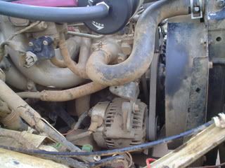
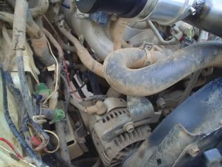
As for the MAP sensor. Do you have a pic of it? Is it mounted to the firewall and what brand? I will try and elaborate on the adjustable MAP sensor case to make it a tad more understandable.
Firstly MAP sensors output a voltage between 0-5V dependent on engine load.
The ecu requires an input signal of between 0-5V, over 5 smoke usually comes out

Let us consider an NA engine, with the appropriate std MAP sensor (14.7psi - atmospheric).
At WOT ie full engine load, depending on sensor type, the sensor output usually swings very close to full rail voltage (either 0 or 5 volts).
For an example we will assume that the MAP sensor is at roughly 5 volts at full load (WOT) and 0 at no load (deceleration or idle).
Now the timing map/fuel map in the ecu for full load will retard timing and increase fuel (injector pulse width) under these conditions to avoid pinging and provide enough fuel to stop leaning out for the load conditions.
If the MAP sensor is already outputting 5v, the ecu has already determined this as a full load condition, and provides the most fuel and timing retard that the factory timing/fuel map has been programmed with, ie there are no further enrichment or retard settings in the factory maps, it is maxed out!
Now with the added boost the MAP signal will hit 5v at alot lighter loads, since it is a atmospheric sensor, hence is maxed out once your boost guage hits 0, as at this point the intake has atmospheric pressure and for an NA engine its determined as full load condition. So this is the limit of the factory fuel and timing map, although now we have to deal with positive pressures above atmospheric, boost!
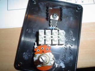
So this twin pot adjustment circuit claims to provide 'tuning' of the MAP sensor output voltage. In fact this is true, it will adjust the output of the MAP and hence will trick the ecu in thinking it is at a different load condition. Ok, so we what additional fuel and timing redardment upon boost. We use this circuit to start tuning at low loads, then we hit atmospheric manifold conditions and positive boost. Hurrmmmm the output voltage of the MAP is already at 5V, the only thing we can do with the circuit is drop voltages. Well this would be a step backwards because we would be tricking the ecu into thinking there is less load and hence reduce fuel and increase timing, fact is we are starting to get on boost, we need more fuel less timing. This is where the problem arises for this particular fix, we have already given the ecu the voltage corresponding to max fuel max retard for max load, there are no further enhancements out of the factory maps.
Second option, replace MAP sensor for a boost compatible type ie 2 bar. Goodo now this sensors provides us with 5V at 14.7psi boost(14.7 above atmospheric-max load) say 2.5V at atmospheric and zero again on idle or deacceleration (min load). Whats the problem here?? Well the factory fuel/timing maps are still the same. So now at atmospheric manifold pressure we have 2.5v instead of 5v at the ecu. Thus the ecu thinks we are at half load when infact originally we were at full load unboosted (NA). Problem again we have less fuel and too much timing advance for the actual engine load, we lean out quicker than before.
Now this is most likely the case from the Turbo surf MAP sensor, although i cant comment on how mud4b's machine performed better with it, abiding the facts above.
Again ecu's are much more complex than what i have stated above, this is a general overview concerning the ecu and MAP sensor. The temp sensors on the other hand alter the factory maps by introducing timing and fueling offests for warm up etc etc, and hence will provide different map offsets regardless of engine load/rpm etc. For instance a cold engine requires more fuel because the fuel doesn't atomize properly, the timing is also reduced because of this and to reduce the possibilities of detonation cause by a lean state due to the non fully atomized fuel mixture. Hence this tweak may help your cause under boost conditions.
I still believe for simplicity case try your luck with an adjustable or rising rate fuel reg. This will fuel the beast better under boost but will do nothing for altering the factory timing. Temp sensor mods may help this.
All the info i have provided is under my understandings of general EFI systems based on GM 1bar MAP sensors. This theory is currently in use to developing my own 'home brew' EFI system including microprocessor algorithms, sensors etc etc. Im not claiming to know all but can try to answer quires to the best of my knowledge.
Sorry for the lonnnnnnnnnnggg post, hope it helps your understand of what the MAP sensor does and how it affects the ecu.
Cheers Dan