Notice: We request that you don't just set up a new account at this time if you are a previous user.
If you used to be one of our moderators, please feel free to reach out to Chris via the facebook Outerlimits4x4 group and he will get you set back up with access should he need you.
Recovery:If you cannot access your old email address and don't remember your password, please click here to log a change of email address so you can do a password reset.
FYI: 60# powersteering into 47# (dialup warning)
Moderators: toaddog, Elmo, DUDELUX
FYI: 60# powersteering into 47# (dialup warning)
Though this might be handy for some ppl because some of the pics of threads covering this seem to have disapeared makes it a bit hard with no pics This conversion was done with to a 47 with a 2H so anyone with a 2f or a 3b disregard the radiator and engine mount mods because the pumps to suit your engines are up high on the block and dont foul anything
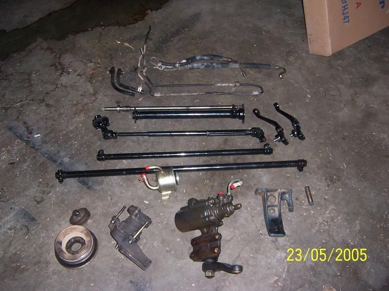
Ok well shopping list up first (typical prices and what we paid for them to come)
Shopping List
60# powersteering box
75# Pitman arm ( not necessary but gives more clearance for the springs)
75# steering arms
75# Draglink
75# Tie-rod
60# 2h powersteering pump (if you have a B or F motor get the pump for that motor)
60# Fan (for clearance not needed with B or F motors i think)
60# Power Steering Belt (different for B and F motors)
60# Harmonic Balancer Pulleys (Again not sure with B or F motors)
55# Steering Column
75# Steering shaft with Uni's
80# Cushion Joint
40# Cooling lines (We used a 60# and modded it to fit)
4 x Crush tubes
4 x High Tensile Bolts
2m of hose and clamps (make sure its oil and pressure rated)
75# Tie-rod end kit (only if needed)
Some 6mm plate for inside of chassis brace and for shock tower
Steering Dampner to suit MK/MQ
You do not have the required permissions to view the files attached to this post.
Last edited by Tooheys on Tue Sep 19, 2006 9:39 pm, edited 2 times in total.
If at first you dont succeed.......get a bigger HAMMER!!!
Step 1: Mount the Pump
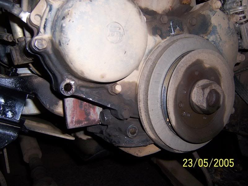
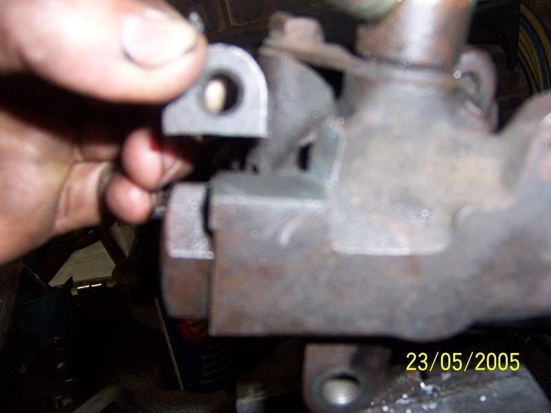
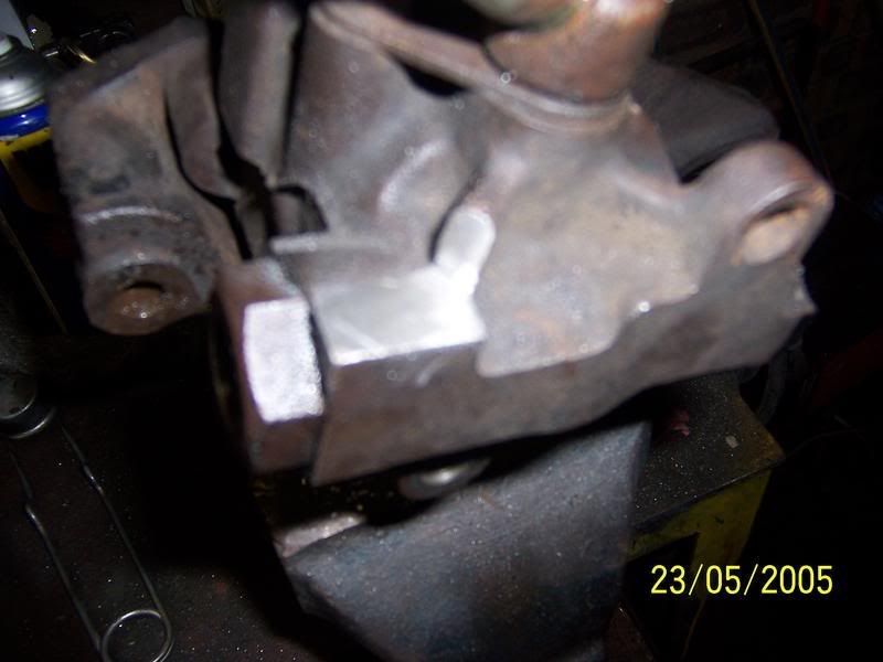
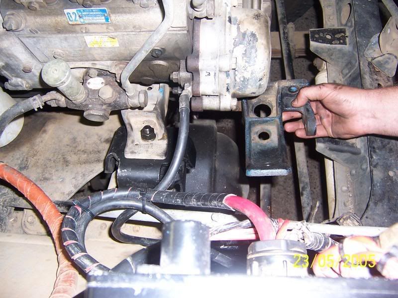
Remove the radiator and front cowl panel to give you room to work and you have to mod the radiaotor anyways. We had to cut and booty fab up some little bits and pieces to make the pump bolt up. Firstly we had to make a tab off the upper engine mount to duplicate the one on the 60# mount (the tab closest to his hand) we just used a piece of angle cut and drilled to give the hole the same dimensions. The 2 holes in the block you can see is the other 2 holes that the pump mounts too. Bolt the extra pulleys onto the harmonic balancer. we also cut a bit off the pump to give more clearance for the engine mounts. Bolt it all up and it should be apples
You do not have the required permissions to view the files attached to this post.
Last edited by Tooheys on Tue Sep 19, 2006 9:43 pm, edited 1 time in total.
If at first you dont succeed.......get a bigger HAMMER!!!
More Pics
You do not have the required permissions to view the files attached to this post.
Last edited by Tooheys on Tue Sep 19, 2006 9:44 pm, edited 1 time in total.
If at first you dont succeed.......get a bigger HAMMER!!!
Step 2: Mod the bottom radiator outlet
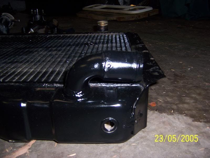
With the pump mounted the bottom outlet points straight at the pump so you have to put some brass elbows in so you can get clearance. We had an old radiator lying around so we cut the outlet off it to use as joiners between the elbows. The joints are all just silver soldered together by a plumber mate or ours. For added clearance we slotted the holes for the radiator support pannel so that it moved forward about 10mm or so. Do a couple of dry fits to make sure your angles are right before you solder it all together. You can still use the Standard radiator hose too which is a bonus.
Note that there should be another bend so that the outlet faces up off the flloor......we found that out once we fitted it up. I just never took a photo of it
You do not have the required permissions to view the files attached to this post.
Last edited by Tooheys on Tue Sep 19, 2006 9:48 pm, edited 1 time in total.
If at first you dont succeed.......get a bigger HAMMER!!!
Step 3: Bolt up the Steering arms and tie-rod and draglink
Remove the old tierod and draglink and the relay box and steering box
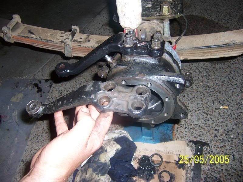
We had a bit of trouble getting the old arms off so we stripped the hubs down and used a brass drift and hammer to punch them out from inside the swivel hub. We buggered one of the bearings doing this so be careful we then decided to just rebuild the swivel hubs while we were at it (bearings and all seals and gaskets). Mount the new arms and use the same amount of shims under them as the old ones. We put heaps of never-sieze on all the new rod ends before we installed them.
You do not have the required permissions to view the files attached to this post.
Last edited by Tooheys on Tue Sep 19, 2006 9:50 pm, edited 1 time in total.
If at first you dont succeed.......get a bigger HAMMER!!!
Step 4: Mount the Steering Box
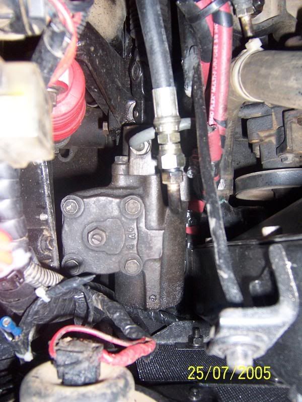
Remove the old shock tower. Cut a bit out of the front guard to clear the box and then dummy fit the box onto the chassis rail and see how it all fits, hook up the drag link and make sure everything is hunky dory and when it is mark the holes for the box. Drill out the chassis rail to the size of the crush tubes your using. Cut a piece of plate to go on the inside of the chassis rail and tack weld your crush tubes to it. Mount up the bit of plate to the chassis rail and do another dummy fit to make sure its all good then weld it up when your happy with it.
You do not have the required permissions to view the files attached to this post.
Last edited by Tooheys on Tue Sep 19, 2006 9:52 pm, edited 1 time in total.
If at first you dont succeed.......get a bigger HAMMER!!!
Step 5: Mount the Steering Column and Intermediate Shaft
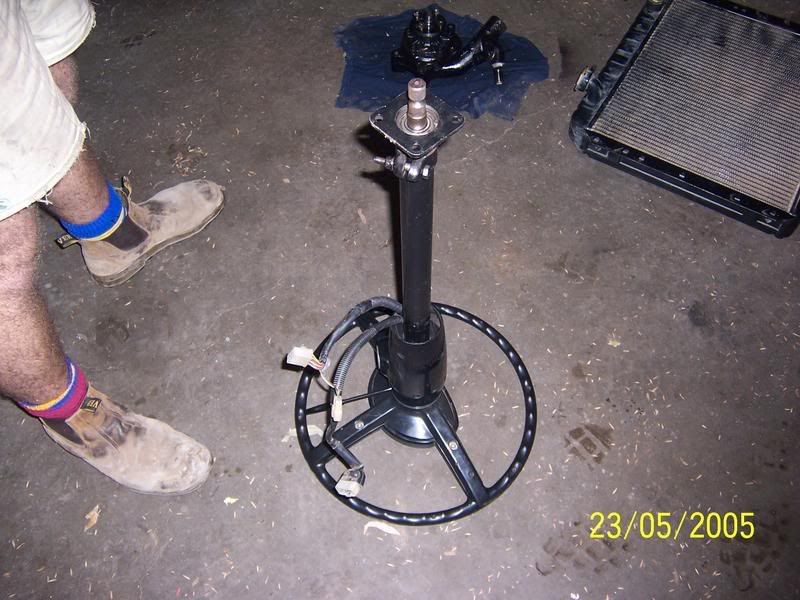
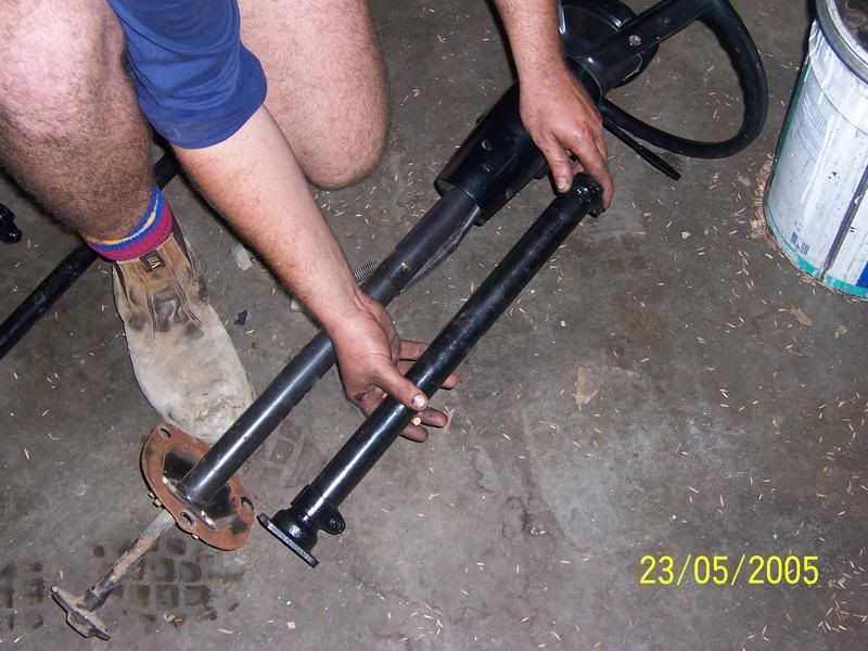
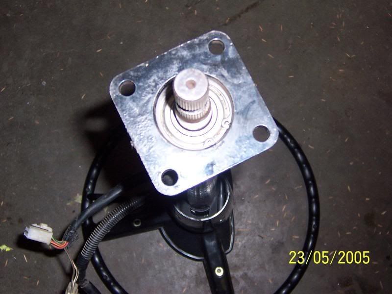
We were lucky to find a 55 Series Column that had already been cut down at the wreckers so im not sure how much you have to shorten it. We stripped it and put the barrel and combo switch from the original column onto it then mounted it up. Now you use the 80# cushion joint to join the large spline of the steering column to the small spline of the intermediate shaft. If you dont want the cushion joint in there just take it to a driveshaft specialist and get them to make you one uni out of the 80# and 75# joints so you have a uni with a large spline on one side and a small spline on the other. Hook it all up and thats that.
You do not have the required permissions to view the files attached to this post.
Last edited by Tooheys on Tue Sep 19, 2006 9:54 pm, edited 1 time in total.
If at first you dont succeed.......get a bigger HAMMER!!!
Step 6: Re-Attach the Shock Tower
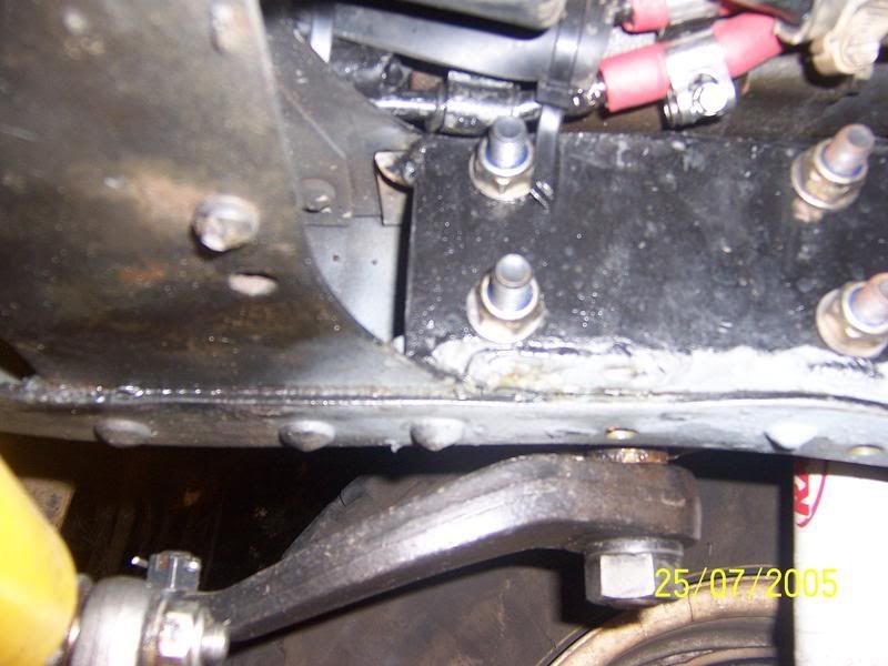
Firstly remove and reverse the pin in the top of the shock tower so the shock can go on the other side of the tower then dummy fit it to the chassis rail to see how much of the inside web you will have to cut out and also how much you will have to space it out from the chassis rail. We cut a little bit of the inside web out then we spaced it out with a 6mm piece of plate that was tapped and welded to the rail. The top of the chassis rail was also tapped, the shock tower was the bolted to the chassis rail using some high tensile bolts
You do not have the required permissions to view the files attached to this post.
If at first you dont succeed.......get a bigger HAMMER!!!
Step 7: Mount the reserviour and cooling lines
We mounted the reserviour to the inside of the guard. We used 60# cooling lines so we had to cut and bend them around a littlle bit to make them fit. We made up a bracket on the front of the chassis to mount them too. If you use standard 40# lines you wont have these problems. We had a high pressure line from a HJ75 but it was pretty long so we took it to pirtec and they soldered the ends onto some new fittings and gave us a new hose so that it was a fair bit neater. Then we joined all the lines with the hose, clamped everything and added some dextron III. Bleed the system
You do not have the required permissions to view the files attached to this post.
If at first you dont succeed.......get a bigger HAMMER!!!
Step 8: mount the Steering Dampner
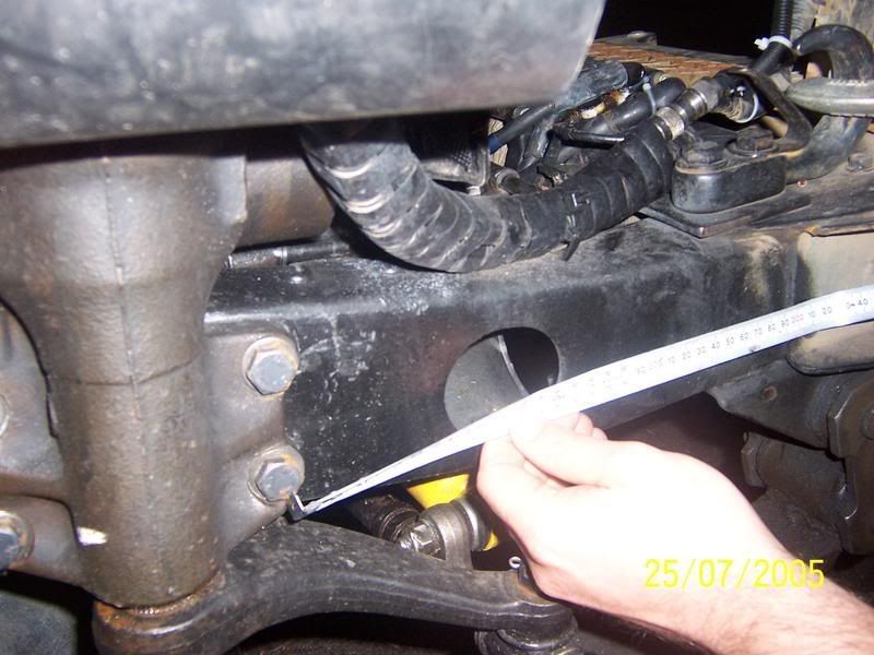
Opps almost forgot. We took measurements from lock to lock from the standard mount to the steering arm mount then rang arb to see if they had anything close to those measurements as luck would have it a steering dampner from a MK/MQ will fit. With it all bolted up the angle is a bit on the sharp side so we might flog the bushes out but we are going to see how it goes and move the chassis mount for the dampner if need be. That should be about it i think
If at first you dont succeed.......get a bigger HAMMER!!!
Put the photos back up for the people that have pmed me asking for them. I'm pretty sure they are in the correct order.
If you really need measurements pm me and i can give them too you
Tooheys
If you really need measurements pm me and i can give them too you
Tooheys
You do not have the required permissions to view the files attached to this post.
If at first you dont succeed.......get a bigger HAMMER!!!
Re: FYI: 60# powersteering into 47# (dialup warning)
Can someone pls update this thread with the pics, as Im planning to do this conversion, it would help me a lot
thanks
thanks
Re: FYI: 60# powersteering into 47# (dialup warning)
I dont have any picks from Toohey's build but here are the pics from my 60series steering in a bj42..
http://www.phat42.com/gallery2/gallery/ ... 0steering/" onclick="window.open(this.href);return false;
Hope they help.
http://www.phat42.com/gallery2/gallery/ ... 0steering/" onclick="window.open(this.href);return false;
Hope they help.
Re: FYI: 60# powersteering into 47# (dialup warning)
now the hard part....
looking for the parts
Re: FYI: 60# powersteering into 47# (dialup warning)
De-lux had some 60 steering parts for sale on here or ebay. That would get you a pump and a box. rest is pretty easy to find from a wrecker (cept the 55 shaft).
Re: FYI: 60# powersteering into 47# (dialup warning)
thanks will check it out
the 55 column would be the hardest!
dont need the pump as Im using a ford item
replacing the 40 series box as I wanna install an extractor for the v8
the 55 column would be the hardest!
dont need the pump as Im using a ford item
replacing the 40 series box as I wanna install an extractor for the v8
Re: FYI: 60# powersteering into 47# (dialup warning)
http://s91.photobucket.com/albums/k287/tooheys1981/ is the photobucket album with all the pics in it. Have a look in there. Not sure why the some of the pics work and some dont as my photobucket account is still active.
If at first you dont succeed.......get a bigger HAMMER!!!
Who is online
Users browsing this forum: No registered users and 56 guests